| Last Modified: 11-27-2007 | 1.6 J | |
| Service Category: Suspension | Section: Tire Pressure Monitoring | |
| Model Year: 2008 | Model: LX570 | Doc ID: RM000000XN501SX |
| Title: TIRE PRESSURE MONITORING: TIRE PRESSURE WARNING SYSTEM: DESCRIPTION (2008 LX570) | ||
|
TC and CG Terminal Circuit |
DESCRIPTION
DTC output mode is set by connecting terminals 13 (TC) and 4 (CG) of the DLC3. The DTCs are output by the blinking of the tire pressure warning light.
WIRING DIAGRAM
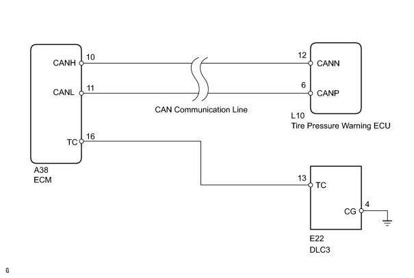
HINT:
When each warning light blinks continuously, a ground short in the wiring of terminal TC of the DLC3 or an internal ground short in each ECU is suspected.
INSPECTION PROCEDURE
PROCEDURE
|
1. |
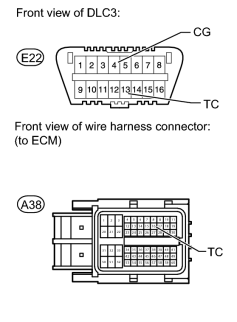
CHECK HARNESS AND CONNECTOR (DLC3 - ECM AND BODY GROUND) |
|
(a) Disconnect the A38 ECM connector. |
(b) Measure the resistance according to the value(s) in the table below.
Standard Resistance:
|
Tester Connection |
Condition |
Specified Condition |
|---|---|---|
|
E22-13 (TC) - A38-16 (TC) |
Always |
Below 1 Ω |
|
E22-13 (TC) or A38-16 (TC) - Body ground |
Always |
10 kΩ or higher |
|
E22-4 (CG) - Body ground |
Always |
Below 1 Ω |
|

|
2. |
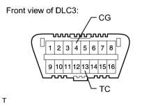
INSPECT DLC3 (TC VOLTAGE) |
|
(a) Connect the A38 ECM connector. |
(b) Measure the voltage according to the value(s) in the table below.
Standard Voltage:
|
Tester Connection |
Switch Condition |
Specified Condition |
|---|---|---|
|
E22-13 (TC) - E22-4 (CG) |
Engine switch on (IG) |
11 to 14 V |
|

|

|