| Last Modified: 11-27-2007 | 1.6 U | |
| Service Category: Vehicle Interior | Section: Theft Deterrent/Keyless Entry | |
| Model Year: 2008 | Model: LX570 | Doc ID: RM000000XUA01RX |
| Title: THEFT DETERRENT / KEYLESS ENTRY: SMART ACCESS SYSTEM WITH PUSH-BUTTON START (for Entry Function): TERMINALS OF ECU (2008 LX570) | ||
TERMINALS OF ECU
1. CHECK CERTIFICATION ECU (SMART KEY ECU ASSEMBLY)
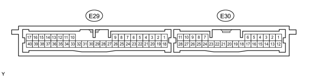
(a) Disconnect the E29 ECU connector.
(b) Measure the resistance and voltage of the wire harness side connector.
|
Terminal No. (Symbol) |
Wiring Color |
Terminal Description |
Condition |
Specified Condition |
|---|---|---|---|---|
|
E29-17 (E) - Body ground |
W-B - Body ground |
Ground |
Always |
Below 1 Ω |
|
E29-1 (+B) - Body ground |
B - Body ground |
+B power supply |
Always |
11 to 14 V |
|
E29-18 (IG) - Body ground |
B - Body ground |
Ignition power supply |
Engine switch off |
Below 1 V |
|
Engine switch on (IG) |
11 to 14 V |
|||
|
E29-3 (TSW1) - E29-17 (E) |
G - W-B |
Door outside handle (driver side) lock switch signal |
Switch released |
10 kΩ or higher |
|
Switch pressed in |
Below 1 Ω |
|||
|
E29-4 (TSW2) - E29-17 (E) |
BR - W-B |
Door outside handle (front passenger side) lock switch signal |
Switch released |
10 kΩ or higher |
|
Switch pressed in |
Below 1 Ω |
|||
|
E30-25 (TSW3) - E29-17 (E) |
G - W-B |
Door outside handle (rear LH) lock switch signal |
Switch released |
10 kΩ or higher |
|
Switch pressed in |
Below 1 Ω |
|||
|
E30-26 (TSW4) - E29-17 (E) |
G - W-B |
Door outside handle (rear RH) lock switch signal |
Switch released |
10 kΩ or higher |
|
Switch pressed in |
Below 1 Ω |
|||
|
E29-7 (TSW5) - E29-17 (E) |
L - W-B |
Back door lock switch signal |
Switch released |
10 kΩ or higher |
|
Switch pressed in |
Below 1 Ω |
If the result is not as specified, the wire harness side may have a malfunction.
(c) Reconnect the E29 ECU connector.
(d) Measure the voltage of the connector.
|
Terminal No. (Symbol) |
Wiring Color |
Terminal Description |
Condition |
Specified Condition |
|---|---|---|---|---|
|
E29-33 (CLG1) - E29-34 (CG1B) |
L - W |
Door electrical key oscillator (driver side) sensor signal |
All doors closed, all doors locked and engine switch off |
Alternating between 5 V and below 1 V |
|
Door unlocked or door open |
Below 1 V |
|||
|
E29-22 (SEN1) - E29-17 (E) |
R - W-B |
Touch sensor detection signal |
Outside door handle touched |
11 to 14 V |
|
Outside door handle not touched |
Below 1 V |
|||
|
E29-5 (SEL1) - E29-17 (E) |
Y - W-B |
Touch sensor activation control signal |
Key at least 5 m (16.4 ft.) away from door |
11 to 14 V |
|
Key moved near outside door handle |
Below 1 V |
|||
|
E29-35 (CLG2) - E29-36 (CG2B) |
L - R |
Door electrical key oscillator (front passenger side) sensor signal |
All doors closed, all doors locked and engine switch off |
Alternating between 5 V and below 1 V |
|
Door unlocked or door open |
Below 1 V |
|||
|
E29-23 (SEN2) - E29-17 (E) |
R - W-B |
Touch sensor detection signal |
Outside door handle touched |
11 to 14 V |
|
Outside door handle not touched |
Below 1 V |
|||
|
E29-6 (SEL2) - E29-17 (E) |
Y - W-B |
Touch sensor activation control signal |
Key at least 5 m (16.4 ft.) away from door |
11 to 14 V |
|
Key moved near outside door handle |
Below 1 V |
|||
|
E30-8 (CLG3) - E30-9 (CG3B) |
L - W |
Door electrical key oscillator (rear LH) sensor signal |
All doors closed, all doors locked and engine switch off |
Alternating between 5 V and below 1 V |
|
Door unlocked or door open |
Below 1 V |
|||
|
E30-28 (SEN3) - E29-17 (E) |
R - W-B |
Touch sensor detection signal |
Outside door handle touched |
11 to 14 V |
|
Outside door handle not touched |
Below 1 V |
|||
|
E30-1 (SEL3) - E29-17 (E) |
Y - W-B |
Touch sensor activation control signal |
Key at least 5 m (16.4 ft.) away from door |
11 to 14 V |
|
Key moved near outside door handle |
Below 1 V |
|||
|
E30-10 (CLG4) - E30-11 (CG4B) |
L - W |
Door electrical key oscillator (rear RH) sensor signal |
All doors closed, all doors locked and engine switch off |
Alternating between 5 V and below 1 V |
|
Door unlocked or door open |
Below 1 V |
|||
|
E30-27 (SEN4) - E29-17 (E) |
R - W-B |
Touch sensor detection signal |
Outside door handle touched |
11 to 14 V |
|
Outside door handle not touched |
Below 1 V |
|||
|
E30-2 (SEL4) - E29-17 (E) |
Y - W-B |
Touch sensor activation control signal |
Key at least 5 m (16.4 ft.) away from door |
11 to 14 V |
|
Key moved near outside door handle |
Below 1 V |
|||
|
E29-11 (CLG5) - E29-12 (CG5B) |
SB - V |
Indoor electrical key antenna (for front floor) sensor signal |
30 seconds after driver side door opened and closed, engine switch off |
Alternating between 5 V and below 1 V |
|
Within 30 seconds after driver side door opened and closed, engine switch off |
Below 1 V |
|||
|
E29-13 (CLG6) - E29-14 (CG6B) |
R - SB |
Indoor electrical key antenna (for rear floor) sensor signal |
30 seconds after driver side door opened and closed, engine switch off |
Alternating between 5 V and below 1 V |
|
Within 30 seconds after driver side door opened and closed, engine switch off |
Below 1 V |
|||
|
E29-15 (CLG7) - E29-16 (CG7B) |
GR - W |
Indoor electrical key antenna (for luggage compartment) sensor signal |
30 seconds after driver side door opened and closed, engine switch off |
Alternating between 5 V and below 1 V |
|
Within 30 seconds after driver side door opened and closed, engine switch off |
Below 1 V |
|||
|
E29-31 (CLG8) - E29-32 (CG8B) |
G - GR |
Back door electrical key antenna (for outside luggage compartment) sensor signal |
Back door opener switch off |
Alternating between 5 V and below 1 V |
|
Back door opener switch on |
Below 1 V |
|||
|
E29-29 (RCO) - E29-17 (E) |
B - W-B |
Door control receiver power source |
None of key switches pressed → Any of key switches pressed |
Below 1 V → 4.5 to 5.5 V → Below 1 V |
|
E29-39 (RSSI) - E29-17 (E) |
L - W-B |
Door control receiver electric wave existence signal |
None of key switches pressed → Any of key switches pressed |
11 to 14 V → Below 1 V |
|
E29-38 (RDA) - E29-17 (E) |
LG - W-B |
Door control receiver data input signal |
None of key switches pressed → Any of key switches pressed |
11 to 14 V → Below 1 V |
|
E29-21 (BZR) - E29-17 (E) |
LG - W-B |
Wireless door lock buzzer signal |
Answer-back on |
Pulse generation |
|
Answer-back off |
Below 1 V |
If the result is not as specified, the ECU may have a malfunction.
2. CHECK MAIN BODY ECU (COWL SIDE JUNCTION BLOCK LH)
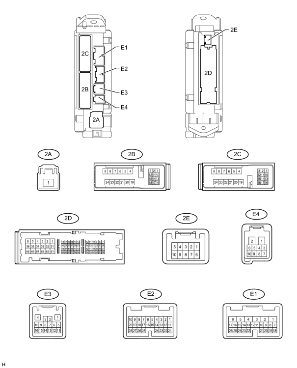
(a) Disconnect the E1, E2, E3, 2A, 2B and 2D ECU connectors.
(b) Measure the resistance and voltage of the wire harness side connectors.
|
Terminal No. (Symbol) |
Wiring Color |
Terminal Description |
Condition |
Specified Condition |
|---|---|---|---|---|
|
2D-62 (GND2) - Body ground |
W-B - Body ground |
Ground |
Always |
Below 1 Ω |
|
E3-1 (GND3) - Body ground |
BR - Body ground |
Ground |
Always |
Below 1 Ω |
|
2A-1 (ALTB) - Body ground |
B - Body ground |
ALTB power supply |
Always |
11 to 14 V |
|
2B-20 (BATB) - Body ground |
L - Body ground |
BATB power supply |
Always |
11 to 14 V |
|
E1-6 (AM1) - Body ground |
W - Body ground |
AM1 power supply |
Always |
11 to 14 V |
|
E2-1 (AM2) - Body ground |
W - Body ground |
AM2 power supply |
Always |
11 to 14 V |
|
2A-1 (IG) - Body ground |
B - Body ground |
IG1 signal |
Engine switch on (IG) |
11 to 14 V |
|
Engine switch off |
Below 1 V |
|||
|
2A-1 (ACC) - Body ground |
B - Body ground |
ACC signal |
Engine switch on (ACC) |
11 to 14 V |
|
Engine switch off |
Below 1 V |
If the result is not as specified, the wire harness side may have a malfunction.
(c) Reconnect the E1, E2, E3, 2A, 2B and 2D ECU connectors.
(d) Measure the voltage of the connectors.
|
Terminal No. (Symbol) |
Wiring Color |
Terminal Description |
Condition |
Specified Condition |
|---|---|---|---|---|
|
E1-24 (DCTY) - Body ground |
L - Body ground |
Driver side door courtesy switch input |
Driver side door open |
Below 1 V |
|
Engine switch off, and driver side door courtesy switch off |
Pulse generation (see waveform 1 or 2) |
|||
|
E2-21 (PCTY) - Body ground |
Y - Body ground |
Front passenger side door courtesy switch input |
Front passenger side door open |
Below 1 V |
|
Engine switch off, and passenger side door courtesy switch off |
Pulse generation (see waveform 3 or 4) |
|||
|
2C-2 (LCTY) - Body ground |
W - Body ground |
Rear door LH courtesy light switch input |
Rear door LH open |
Below 1 V |
|
Engine switch off, and rear LH side door courtesy switch off |
Pulse generation (see waveform 5 or 6) |
|||
|
E2-7 (RCTY) - Body ground |
G - Body ground |
Rear door RH courtesy light switch input |
Rear door RH open |
Below 1 V |
|
Engine switch off, and rear RH side door courtesy switch off |
Pulse generation (see waveform 7 or 8) |
|||
|
E2-25 (BCTY) - Body ground |
W - Body ground |
Back door courtesy light switch input |
Back door open |
Below 1 V |
|
Engine switch off, and back door closed |
Pulse generation (see waveform 9 or 10) |
|||
|
E3-4 (HAZ) - Body ground |
O - Body ground |
Hazard warning light signal |
Answer-back on |
Below 1 V |
|
Answer-back off |
11 to 14 V |
|||
|
E1-26 (BDSU) - Body ground |
L - Body ground |
Back door opener switch input |
Back door lock opener switch off |
Below 1 V |
|
Back door lock opener switch on |
Pulse generation (see waveform 11 or 12) |
If the result is not as specified, the ECU may have a malfunction.
|
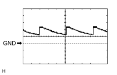
(e) Using an oscilloscope, check waveform 1.
|
|
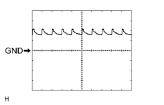
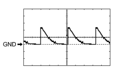
(f) Using an oscilloscope, check waveform 2.
|
|
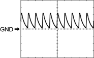
(g) Using an oscilloscope, check waveform 3.
|
|
(h) Using an oscilloscope, check waveform 4.
|
|
|
(i) Using an oscilloscope, check waveform 5.
|
|
|
(j) Using an oscilloscope, check waveform 6.
|
|
|
(k) Using an oscilloscope, check waveform 7.
|
|
|
(l) Using an oscilloscope, check waveform 8.
|
|
|
(m) Using an oscilloscope, check waveform 9.
|
|
|
(n) Using an oscilloscope, check waveform 10.
|
|
|
(o) Using an oscilloscope, check waveform 11.
|
|
|
(p) Using an oscilloscope, check waveform 12.
|
3. CHECK POWER BACK DOOR UNIT (w/ Power Back Door)
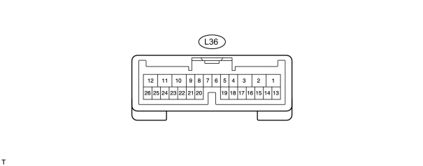
(a) Disconnect the L36 unit connector.
(b) Measure the voltage and resistance according to the value(s) in the table below.
|
Terminal No. (Symbol) |
Wiring Color |
Terminal Description |
Condition |
Specified Condition |
|---|---|---|---|---|
|
L36-10 (ECUB) - Body ground |
R - Body ground |
ECUB power supply |
Always |
11 to 14 V |
|
L36-11 (GND) - Body ground |
W-B - Body ground |
Body ground |
Always |
Below 1 Ω |
If the result is not as specified, there may be a malfunction on the wire harness side.
(c) Reconnect the L36 unit connector.
(d) Measure the voltage according to the value(s) in the table below.
|
Terminal No. (Symbol) |
Wiring Color |
Terminal Description |
Condition |
Specified Condition |
|---|---|---|---|---|
|
L36-2 (DC+) - L36-1 (DC-) |
R - B |
Power back door lock motor circuit |
Back door lock motor is operating |
11 to 14 V |
|
L36-2 (DC+) - L36-1 (DC-) |
R - B |
Power back door lock motor circuit |
Back door lock motor is stopped |
Below 1 V |
If the result is not as specified, the ECU may have a malfunction.

|

|