| Last Modified: 11-27-2007 | 1.6 U | |
| Service Category: Vehicle Interior | Section: Door Lock | |
| Model Year: 2008 | Model: LX570 | Doc ID: RM000000XX400IX |
| Title: DOOR LOCK: WIRELESS DOOR LOCK CONTROL SYSTEM: TERMINALS OF ECU (2008 LX570) | ||
TERMINALS OF ECU
1. CHECK MAIN BODY ECU (COWL SIDE JUNCTION BLOCK LH)
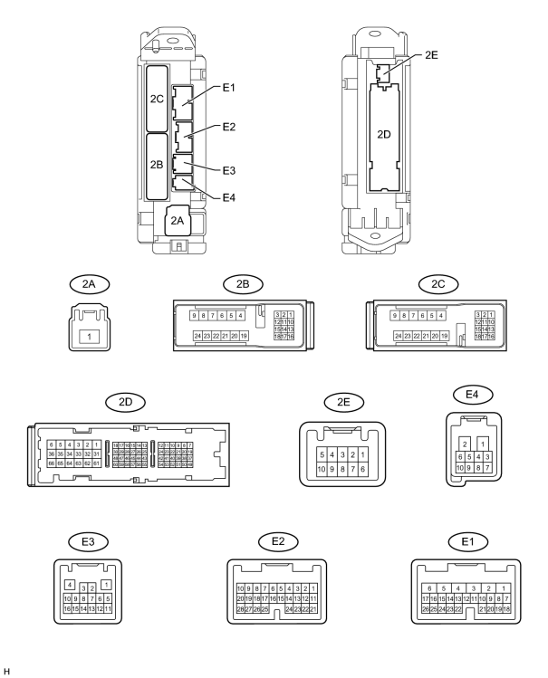
(a) Disconnect the DA, DD, DF, L12 and L13 ECU connectors.
(b) Measure the resistance and voltage according to value(s) in the table below.
|
Terminal No. (Symbol) |
Wiring Color |
Terminal Description |
Condition |
Specified Condition |
|---|---|---|---|---|
|
2D-62 (GND2) - Body ground |
W-B - Body ground |
Ground |
Always |
Below 1 Ω |
|
E3-1 (GND3) - Body ground |
BR - Body ground |
Ground |
Always |
Below 1 Ω |
|
2A-1 (ACC) - 2D-62 (GND2 |
B - W-B |
ACC power supply |
Engine switch off |
Below 1 V |
|
Engine switch on (ACC) |
11 to 14 V |
|||
|
E1-6 (AM1) - 2D-62 (GND2) |
W - W-B |
Battery power supply |
Always |
11 to 14 V |
|
E2-1 (AM2) - 2D-62 (GND2) |
W - W-B |
Battery power supply |
Always |
11 to 14 V |
|
2A-1 (IG) - 2D-62 (GND2) |
B - W-B |
IG power supply |
Engine switch off |
Below 1 V |
|
Engine switch on (IG) |
11 to 14 V |
If the result is not as specified, there may be a malfunction on the wire harness side.
(c) Reconnect the DA, DD, DF, L12 and L3 ECU connectors.
(d) Measure the voltage according to the value(s) in the table below.
|
Terminal No. (Symbol) |
Wiring Color |
Terminal Description |
Condition |
Specified Condition |
|---|---|---|---|---|
|
E1-24 (DCTY) - Body ground |
L - Body ground |
Driver side door courtesy light switch input |
Driver side courtesy switch on |
Below 1 V |
|
Engine switch off, and driver side door courtesy switch off |
Pulse generation (refer to waveform 1 and 2) |
|||
|
E2-21 (PCTY) - Body ground |
Y - Body ground |
Front passenger side door courtesy light switch input |
Front Passenger side courtesy switch on |
Below 1 V |
|
Engine switch off, and passenger side door courtesy switch off |
Pulse generation (refer to waveform 3 and 4) |
|||
|
2C-2 (LCTY) - Body ground |
W - Body ground |
Rear side door LH courtesy light switch input |
Rear side door LH courtesy switch on |
Below 1 V |
|
Engine switch off, and rear side door LH courtesy switch off |
Pulse generation (refer to waveform 5 and 6) |
|||
|
E2-7 (RCTY) - Body ground |
G - Body ground |
Rear side door RH courtesy light switch input |
Rear side door RH courtesy switch on |
Below 1 V |
|
Engine switch off, and rear side door RH courtesy switch off |
Pulse generation (refer to waveform 7 and 8) |
|||
|
E2-25 (BCTY) - Body ground |
w - Body ground |
Back door courtesy light switch input |
Back door closed |
Below 1 V |
|
Engine switch off, and back door courtesy switch off |
Pulse generation (refer to waveform 9 and 10) |
|||
|
E3-4 (HAZ) - Body ground |
O - Body ground |
Turn signal light drive |
Hazard warning signal switch on |
Pulse generation |
|
Hazard warning signal switch off |
Below 1 V |
|||
|
2B-16 (DIM) - 2D-62 (GND2) |
R-G - W-B |
Headlight low drive |
Headlight dimmer switch low |
11 to 14 V |
|
2B-18 (HRLY) - 2D-62 (GND2) |
L - W-B |
Headlight (high) drive |
Headlight dimmer switch high |
11 to 14 V |
|
2A-1 (TRLY) - 2D-62 (GND2) |
B - W-B |
Taillight drive |
Headlight dimmer switch tail |
11 to 14 V |
If the result is not as specified, the ECU may have a malfunction.
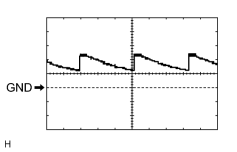
|
(e) Using an oscilloscope, check waveform 1.
|
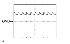
|
(f) Using an oscilloscope, check waveform 2.
|
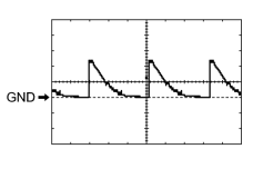
|
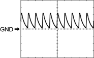
(g) Using an oscilloscope, check waveform 3.
|
|
(h) Using an oscilloscope, check waveform 4.
|
|
|
(i) Using an oscilloscope, check waveform 5.
|
|
|
(j) Using an oscilloscope, check waveform 6.
|
|
|
(k) Using an oscilloscope, check waveform 7.
|
|
|
(l) Using an oscilloscope, check waveform 8.
|
|
|
(m) Using an oscilloscope, check waveform 9.
|
|
|
(n) Using an oscilloscope, check waveform 10.
|
2. CHECK CERTIFICATION ECU (SMART KEY ECU ASSEMBLY)
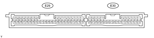
(a) Disconnect the E29 and E30 ECU connectors.
(b) Measure the resistance and voltage according to the value(s) in the table below.
|
Terminal No. (Symbol) |
Wiring Color |
Terminal Description |
Condition |
Specified Condition |
|---|---|---|---|---|
|
E29-17 (E) - Body ground |
W-B - Body ground |
Ground |
Always |
Below 1 Ω |
|
E29-1 (+B) - E29-17 (E) |
B - W-B |
Battery power supply |
Always |
11 to 14 V |
|
E29-18 (IG) - E29-17 (E) |
B - W-B |
IG power supply |
Engine switch on (IG) |
11 to 14 V |
|
Engine switch off |
Below 1 V |
If the result is not as specified, there may be a malfunction on the wire harness side.
(c) Reconnect the E29 and E30 ECU connectors.
(d) Measure the voltage according to the value(s) in the table below.
|
Terminal No. (Symbol) |
Wiring Color |
Terminal Description |
Condition |
Specified Condition |
|---|---|---|---|---|
|
E29-39 (RSSI) - E29-17 (E) |
L - W-B |
Door control receiver output signal |
Engine switch off, all doors closed and transmitter switch not pressed |
11 to 14 V |
|
Engine switch off, all doors closed and transmitter switch pressed |
Below 1 V |
|||
|
E29-38 (RDA) - E29-17 (E) |
LG - W-B |
Door control receiver output signal |
Engine switch off, all doors closed and transmitter switch not pressed → switch pressed → switch not pressed |
4.6 to 5.4 V → Below 2 V → 4.6 to 5.4 V |
|
E29-29 (RCO) - E29-17 (E) |
B - W-B |
Supply battery to door control receiver |
Engine switch off, all doors closed and transmitter switch pressed |
4.6 to 5.4 V |
|
E29-21 (BZR) - Body ground |
LG - Body ground |
Wireless door lock buzzer output |
Wireless door lock buzzer ON |
11 to 14 V |
|
E29-21 (BZR) - Body ground |
LG - Body ground |
Wireless door lock buzzer output |
Wireless door lock buzzer OFF |
Below 1 V |
If the result is not as specified, the ECU may have a malfunction.
3. CHECK DOOR CONTROL RECEIVER

(a) Disconnect the L21 receiver connector.
(b) Measure the resistance and voltage according to the value(s) in the table below.
|
Terminal No. (Symbol) |
Wiring Color |
Terminal Description |
Condition |
Specified Condition |
|---|---|---|---|---|
|
L21-1 (GND) - Body ground |
W-B - Body ground |
Ground |
Always |
Below 1 Ω |
|
L21-4 (+5) - Body ground |
B - Body ground |
Battery power supply |
Always |
4.6 to 5.4 V |
If the result is not as specified, there may be a malfunction on the wire harness side.
4. CHECK POWER BACK DOOR UNIT (w/ Power Back Door System)
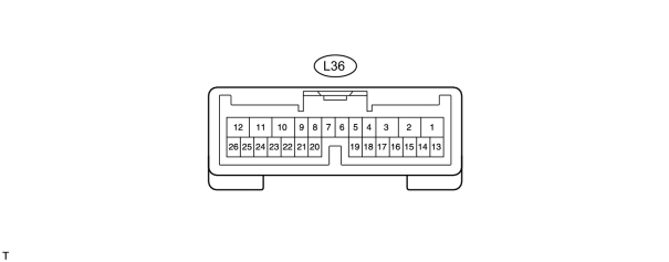
(a) Disconnect the L36 unit connector.
(b) Measure the voltage and resistance according to the value(s) in the table below.
|
Terminal No. (Symbol) |
Wiring Color |
Terminal Description |
Condition |
Specified Condition |
|---|---|---|---|---|
|
L36-11 (GND) - Body ground |
W-B - Body ground |
Ground |
Always |
Below 1 Ω |
|
L36-10 (ECUB) - Body ground |
R - Body ground |
Battery power supply |
Always |
11 to 14 V |
If the result is not as specified, there may be a malfunction on the wire harness side.
(c) Reconnect the L36 unit connector.
(d) Measure the voltage according to the value(s) in the table below.
|
Terminal No. (Symbol) |
Wiring Color |
Terminal Description |
Condition |
Specified Condition |
|---|---|---|---|---|
|
L36-26 (BZR+) - Body ground |
L - Body ground |
Power back door warning buzzer signal |
Back door warning buzzer is sounding |
11 to 14 V (pulse generation) |
|
L36-26 (BZR+) - Body ground |
L - Body ground |
Power back door warning buzzer signal |
Back door warning buzzer is stopped |
Below 1 V |
If the result is not as specified, the ECU may have a malfunction.

|

|