- Harness or connector
- Telescopic position sensor or telescopic motor
- Multiplex tilt and telescopic ECU
| Last Modified: 11-27-2007 | 1.6 C | |
| Service Category: Steering | Section: Steering Column | |
| Model Year: 2008 | Model: LX570 | Doc ID: RM000000XZA01HX |
| Title: STEERING COLUMN: POWER TILT AND POWER TELESCOPIC STEERING COLUMN SYSTEM: DESCRIPTION (2008 LX570) | ||
|
DTC |
B2611 |
Telescopic Position Sensor or Telescopic Motor Circuit Malfunction |
DESCRIPTION
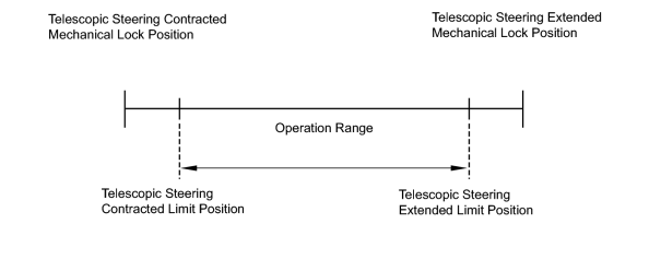
The telescopic motor is operated by the power source voltage supplied from the multiplex tilt and telescopic ECU and slides the steering column forward and backward. The telescopic position sensor (Hall IC) in the telescopic motor detects the sliding position in the forward and backward directions of the steering column and outputs a signal to the multiplex tilt and telescopic ECU based on that sliding amount.
HINT:
Limit positions can be confirmed on the screen of the Techstream.
|
DTC Code |
Detection Condition |
Trouble Area |
|---|---|---|
|
B2611 |
The telescopic operation stops within the operation range while operating. |
|
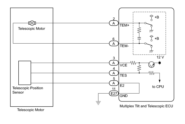
WIRING DIAGRAM
INSPECTION PROCEDURE
HINT:
The wire harness between the multiplex tilt and telescopic ECU and telescopic motor is provided with the steering column assembly.
PROCEDURE
|
1. |
PERFORM ACTIVE TEST USING TECHSTREAM (TELESCO SHORT/LONG) |
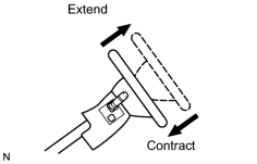
(a) Select the Active Test, use the Techstream to generate a control command, and then check that the steering column contracts and extends.
Tilt & Telescopic
|
Tester Display |
Test Part |
Control Range |
Diagnostic Note |
|---|---|---|---|
|
Telesco Operation |
Telescopic operation |
Long/Short |
- |
OK:
The steering column contracts (extends).
|

|
2. |
CHECK TELESCOPIC MOTOR |
|
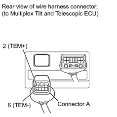
(a) Disconnect connector A from the multiplex tilt and telescopic ECU. |
(b) Apply 12 V battery voltage to the multiplex tilt and telescopic ECU connector. Then check the steering wheel telescopic operation.
OK
|
Measurement Condition |
Specified Condition |
|---|---|
|
12 V battery positive (+) lead → Terminal A-2 (TEM+) 12 V battery negative (-) lead → Terminal A-6 (TEM-) |
The steering column contracts. |
|
12 V battery positive (+) lead → Terminal A-6 (TEM-) 12 V battery negative (-) lead → Terminal A-2 (TEM+) |
The steering column extends |
|
|
3. |
CHECK MULTIPLEX TILT AND TELESCOPIC ECU (VCE TERMINAL VOLTAGE) |
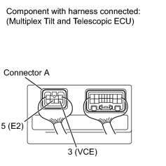
|
(a) Measure the voltage according to the value(s) in the table below. Standard Voltage:
|
|
|
4. |
CHECK TELESCOPIC POSITION SENSOR |
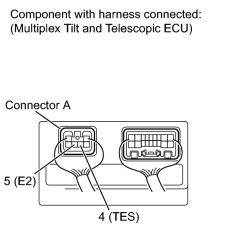
|
(a) Measure the voltage according to the value(s) in the table below. Standard Voltage:
|
|
|
5. |
CHECK HARNESS AND CONNECTOR (ECU - TELESCOPIC POSITION SENSOR) |
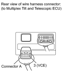
|
(a) Disconnect connector A from the multiplex tilt and telescopic ECU. |
(b) Measure the resistance according to the value(s) in the table below.
Standard Resistance:
|
Tester Connection |
Condition |
Specified Condition |
|---|---|---|
|
A-3 (VCE) - Body ground |
Always |
10 kΩ or higher |
|
|
6. |
CHECK HARNESS AND CONNECTOR (ECU - BODY GROUND) |
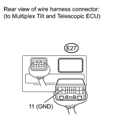
|
(a) Disconnect the E27 connector from the multiplex tilt and telescopic ECU. |
(b) Measure the resistance according to the value(s) in the table below.
Standard Resistance:
|
Tester Connection |
Condition |
Specified Condition |
|---|---|---|
|
E27-11 (GND) - Body ground |
Always |
Below 1 Ω |
|

|

|