- Main body ECU
| Last Modified: 11-27-2007 | 1.6 C | |
| Service Category: Vehicle Interior | Section: Theft Deterrent/Keyless Entry | |
| Model Year: 2008 | Model: LX570 | Doc ID: RM000000YD302TX |
| Title: THEFT DETERRENT / KEYLESS ENTRY: SMART ACCESS SYSTEM WITH PUSH-BUTTON START (for Start Function): DESCRIPTION (2008 LX570) | ||
|
DTC |
B2285 |
Steering Lock Position Signal Circuit Malfunction |
|
DTC |
B2288 |
Steering Lock Signal Circuit Malfunction |
DESCRIPTION
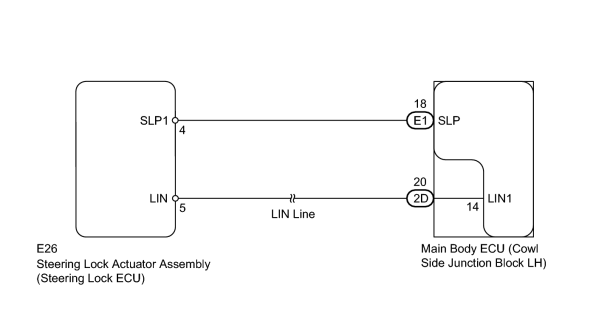
The main body ECU and the steering lock ECU are connected by a cable and the LIN communication line. These DTCs are stored when: 1) signals, transmitted through the cable and the communication line, do not match; or 2) a malfunction is detected in the circuit between the main body ECU and the steering lock ECU.
|
DTC Code |
Detection Condition |
Trouble Area |
|---|---|---|
|
B2285 |
The cable and LIN information between the main body ECU and steering lock ECU is inconsistent. |
|
|
B2288 |
After turning the engine switch from off to on (IG), the steering wheel does not unlock for a certain period of time (the ECU unlocks the steering wheel only when it receives an unlock signal through LIN communication and the cable). |
|
WIRING DIAGRAM
INSPECTION PROCEDURE
PROCEDURE
|
1. |
READ VALUE USING TECHSTREAM (STEERING UNLOCK SWITCH) |
(a) Use the Data List to check if the steering lock is functioning properly.
Main Body
|
Tester Display |
Measurement Item/Range |
Normal Condition |
Diagnostic Note |
|---|---|---|---|
|
Steering Unlock Switch |
Steering lock condition/ON or OFF |
ON: Steering unlocked OFF: Steering locked |
- |
Result
|
Result |
Proceed to |
|---|---|
|
Display on the Techstream does not change according to steering lock position |
A |
|
Display on the Techstream changes according to steering lock position |
B |
|

|
2. |
CHECK HARNESS AND CONNECTOR (MAIN BODY ECU - STEERING LOCK ECU) |
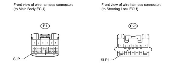
(a) Disconnect the E1 main body ECU connector.
(b) Disconnect the E26 steering lock ECU connector.
(c) Measure the resistance according to the value(s) in the table below.
Standard Resistance:
|
Tester Connection |
Condition |
Specified Condition |
|---|---|---|
|
E1-18 (SLP) - E26-4 (SLP1) |
Always |
Below 1 Ω |
|
E1-18 (SLP) or E26-4 (SLP1) - Body ground |
Always |
10 kΩ or higher |
|
|
3. |
REPLACE MAIN BODY ECU (COWL SIDE JUNCTION BLOCK LH) |
(a) Temporarily replace the main body ECU with a new or normally functioning one.
(b) Check whether DTC B2285 and B2288 are output.
OK:
No DTC is output.
|

|

|