- Harness or connector
- Power source circuit
- Steering actuator
- Steering control ECU
| Last Modified: 11-27-2007 | 1.6 C | |
| Service Category: Steering | Section: Steering Column | |
| Model Year: 2008 | Model: LX570 | Doc ID: RM000000YU500JX |
| Title: VARIABLE GEAR RATIO STEERING: VARIABLE GEAR RATIO STEERING SYSTEM: DESCRIPTION (2008 LX570) | ||
|
DTC |
C15A2/62 |
Actuator Malfunction |
|
DTC |
C15A6/62 |
Actuator Malfunction |
DESCRIPTION
The steering control ECU drives the actuator based on steering angle sensor signals and vehicle speed signals.
If the steering control ECU detects excessive current flowing into the steering actuator, or an internal malfunction, it will turn on the master warning light, store DTC C15A2/62, and stop VGRS operation.
If the steering control ECU detects a malfunction in the motor drive circuit, it will turn the master warning light on, store DTC C15A6/62, and stop VGRS operation.
|
DTC Code |
DTC Detection Condition |
Trouble Area |
|---|---|---|
|
C15A2/62 |
The VGRS system detects a malfunction in the motor drive circuit. |
|
|
C15A6/62 |
The actual motor current value greatly differs from the estimated value. |
|
WIRING DIAGRAM
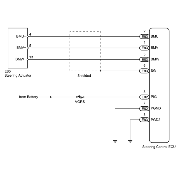
INSPECTION PROCEDURE
HINT:
Only the actuator can be checked in this procedure. If it is normal, the steering control ECU is faulty.
PROCEDURE
|
1. |
CHECK HARNESS AND CONNECTOR (POWER SOURCE CIRCUIT) |
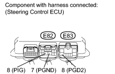
(a) Measure the resistance according to the value(s) in the table below.
Standard Resistance:
|
Tester Connection |
Condition |
Specified Condition |
|---|---|---|
|
E82-7 (PGND) - Body ground |
Always |
Below 1 Ω |
|
E83-8 (PGD2) - Body ground |
(b) Measure the voltage according to the value(s) in the table below.
Standard Voltage:
|
Tester Connection |
Condition |
Specified Condition |
|---|---|---|
|
E82-8 (PIG) - Body ground |
Always |
11 to 14 V |
|

|
2. |
CHECK HARNESS AND CONNECTOR (STEERING CONTROL ECU - STEERING ACTUATOR) |
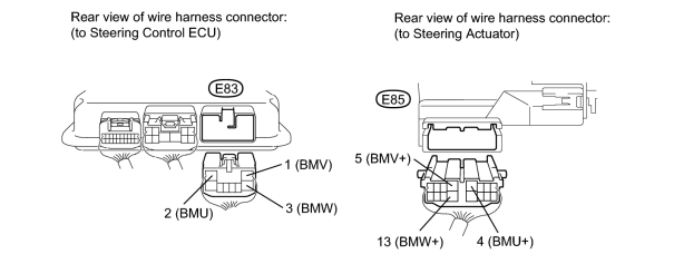
(a) Disconnect the E83 steering control ECU connector.
(b) Disconnect the E85 steering actuator connector.
(c) Measure the resistance according to the value(s) in the table below.
Standard Resistance:
|
Tester Connection |
Condition |
Specified Condition |
|---|---|---|
|
E83-1 (BMV) - E83-2 (BMU) |
Always |
10 kΩ or higher |
|
E83-1 (BMV) - E83-3 (BMW) |
||
|
E83-2 (BMU) - E83-3 (BMW) |
||
|
E83-1 (BMV) - E85-5 (BMV+) |
Always |
Below 1 Ω |
|
E83-2 (BMU) - E85-4 (BMU+) |
||
|
E83-3 (BMW) - E85-13 (BMW+) |
||
|
E83-1 (BMV) - Body ground |
Always |
10 kΩ or higher |
|
E83-2 (BMU) - Body ground |
||
|
E83-3 (BMW) - Body ground |
|
|
3. |
CHECK STEERING ACTUATOR |
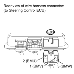
|
(a) Disconnect the E83 steering control ECU connector. |
(b) Measure the resistance according to the value(s) in the table below.
HINT:
The resistance must be measured with the steering actuator connector connected.
Standard Resistance:
|
Tester Connection |
Condition |
Specified Condition |
|---|---|---|
|
E83-1 (BMV) - E83-2 (BMU) |
Always |
Below 1 Ω |
|
E83-1 (BMV) - E83-3 (BMW) |
||
|
E83-2 (BMU) - E83-3 (BMW) |
||
|
E83-1 (BMV) - Body ground |
Always |
10 kΩ or higher |
|
E83-2 (BMU) - Body ground |
||
|
E83-3 (BMW) - Body ground |
|
|
4. |
CHECK DTC |
(a) Check for DTCs
 .
.
Result
|
Result |
Proceed to |
|---|---|
|
C15A1/61 is output |
A |
|
C15A1/61 is not output |
B |
|

|

|