- Harness or connector
- Steering actuator
- Steering control ECU
| Last Modified: 11-27-2007 | 1.6 C | |
| Service Category: Steering | Section: Steering Column | |
| Model Year: 2008 | Model: LX570 | Doc ID: RM000000YU600IX |
| Title: VARIABLE GEAR RATIO STEERING: VARIABLE GEAR RATIO STEERING SYSTEM: DESCRIPTION (2008 LX570) | ||
|
DTC |
C15A3/63 |
Actuator Malfunction |
|
DTC |
C15C5/69 |
Motor Revolution Angle Signal (Test Mode DTC) |
DESCRIPTION
The steering actuator drives the internal motor using the current output from the steering control ECU to change the relative angle between the tire angle and steering wheel angle.
The rotation angle sensor in the steering actuator detects the motor rotation angle and outputs this information to the steering control ECU.
If the steering control ECU detects a malfunction in the rotation angle sensor circuit, it will store DTC C15A3/63.
|
DTC Code |
DTC Detection Condition |
Trouble Area |
|---|---|---|
|
C15A3/63 |
The steering control ECU detects a malfunction in the rotation angle sensor circuit. |
|
|
C15C5/69 |
A steering signal indicating a motor rotation angle of 36° or more (to the left or right) is input after entering test mode.* |
|
HINT:
*: A tire angle of 36° and a motor rotation angle of 36° correspond to the steering wheel angle. The amount of change in tire angle and motor rotation angle is from when the mode is changed to test mode.
WIRING DIAGRAM
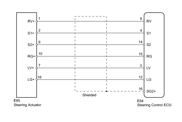
INSPECTION PROCEDURE
PROCEDURE
|
1. |
CHECK HARNESS AND CONNECTOR (STEERING CONTROL ECU - STEERING ACTUATOR) |
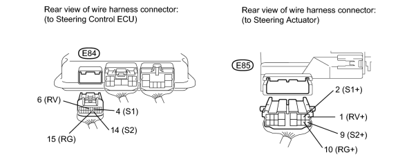
(a) Disconnect the E84 steering control ECU connector.
(b) Disconnect the E85 steering actuator connector.
(c) Measure the resistance according to the value(s) in the table below.
Standard Resistance:
|
Tester Connection |
Condition |
Specified Condition |
|---|---|---|
|
E84-4 (S1) - E85-2 (S1+) |
Always |
Below 1 Ω |
|
E84-6 (RV) - E85-1 (RV+) |
||
|
E84-14 (S2) - E85-9 (S2+) |
||
|
E84-15 (RG) - E85-10 (RG+) |
||
|
E84-4 (S1) - E84-6 (RV) |
Always |
10 kΩ or higher |
|
E84-4 (S1) - E84-14 (S2) |
||
|
E84-4 (S1) - E84-15 (RG) |
||
|
E84-6 (RV) - E84-14 (S2) |
||
|
E84-6 (RV) - E84-15 (RG) |
||
|
E84-14 (S2) - E84-15 (RG) |
||
|
E84-4 (S1) - Body ground |
||
|
E84-6 (RV) - Body ground |
||
|
E84-14 (S2) - Body ground |
||
|
E84-15 (RG) - Body ground |
|

|
2. |
CHECK STEERING ACTUATOR |
|
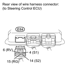
(a) Disconnect the E84 steering control ECU connector. |
(b) Measure the resistance according to the value(s) in the table below.
HINT:
The resistance must be measured with the steering actuator connector connected.
Standard Resistance:
|
Tester Connection |
Condition |
Specified Condition |
|---|---|---|
|
E84-4 (S1) - E84-6 (RV) |
Always |
Below 200 Ω |
|
E84-4 (S1) - E84-14 (S2) |
||
|
E84-4 (S1) - E84-15 (RG) |
||
|
E84-6 (RV) - E84-14 (S2) |
||
|
E84-6 (RV) - E84-15 (RG) |
||
|
E84-14 (S2) - E84-15 (RG) |
||
|
E84-4 (S1) - Body ground |
Always |
10 kΩ or higher |
|
E84-6 (RV) - Body ground |
||
|
E84-14 (S2) - Body ground |
||
|
E84-15 (RG) - Body ground |
|

|

|