- Steering angle sensor
- Harness or connector
- CAN communication system
- Steering control ECU
| Last Modified: 11-27-2007 | 1.6 C | |
| Service Category: Steering | Section: Steering Column | |
| Model Year: 2008 | Model: LX570 | Doc ID: RM000000YUB00KX |
| Title: VARIABLE GEAR RATIO STEERING: VARIABLE GEAR RATIO STEERING SYSTEM: DESCRIPTION (2008 LX570) | ||
|
DTC |
C15C1/74 |
Steering Angle Sensor Malfunction |
|
DTC |
C15C2/74 |
Steering Angle Sensor B+ Malfunction |
DESCRIPTION
The steering control ECU detects a steering angle sensor malfunction by receiving an error signal from the steering angle sensor via CAN communication. If the steering control ECU detects this error signal, it will turn the master warning light on, store these DTCs, and stop VGRS operation.
|
DTC Code |
DTC Detection Condition |
Trouble Area |
|---|---|---|
|
C15C1/74 |
The steering control ECU receives a steering angle sensor malfunction signal via CAN communication. |
|
|
C15C2/74 |
The steering control ECU receives a B+ open circuit signal from the steering angle sensor via CAN communication. |
|
WIRING DIAGRAM
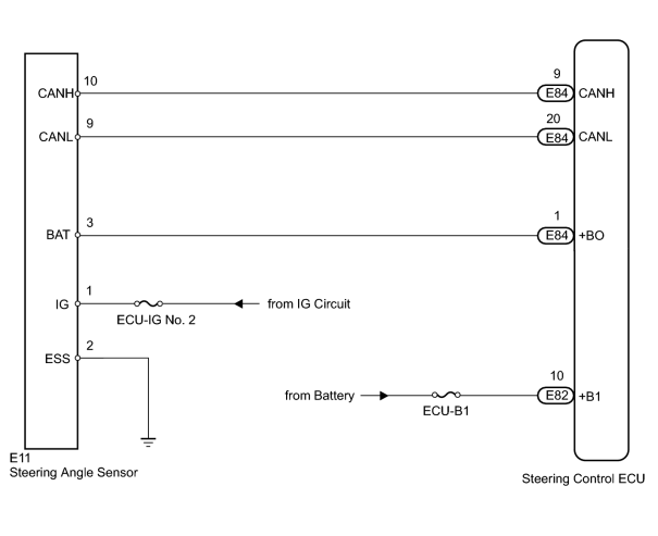
INSPECTION PROCEDURE
PROCEDURE
|
1. |
CHECK DTC (CAN COMMUNICATION SYSTEM) |
(a) Using the Techstream, check if the CAN communication system is functioning normally
 .
.
Result
|
Result |
Proceed to |
|---|---|
|
DTC is not output |
A |
|
DTC is output |
B |
|

|
2. |
CHECK HARNESS AND CONNECTOR (STEERING CONTROL ECU +B1 TERMINAL VOLTAGE) |
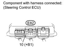
|
(a) Measure the voltage according to the value(s) in the table below. Standard Voltage:
|
|
|
3. |
CHECK STEERING CONTROL ECU (+BO TERMINAL VOLTAGE) |
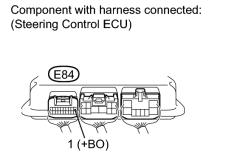
|
(a) Measure the voltage according to the value(s) in the table below. Standard Voltage:
|
|
|
4. |
CHECK HARNESS AND CONNECTOR (STEERING ANGLE SENSOR) |
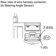
|
(a) Disconnect the E11 steering angle sensor connector. |
(b) Measure the voltage according to the value(s) in the table below.
Standard Voltage:
|
Tester Connection |
Switch Condition |
Specified Condition |
|---|---|---|
|
E11-1 (IG) - Body ground |
Engine switch on (IG) |
11 to 14 V |
(c) Measure the resistance according to the value(s) in the table below.
Standard Resistance:
|
Tester Connection |
Condition |
Specified Condition |
|---|---|---|
|
E11-2 (ESS) - Body ground |
Always |
Below 1 Ω |
|
|
5. |
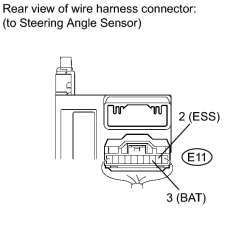
CHECK STEERING ANGLE SENSOR |
|
(a) Disconnect the E11 steering angle sensor connector. |
(b) Measure the voltage according to the value(s) in the table below.
Standard Voltage:
|
Tester Connection |
Switch Condition |
Specified Condition |
|---|---|---|
|
E11-3 (BAT) - E11-2 (ESS) |
Engine switch on (IG) |
11 to 14 V |
|

|

|