| Last Modified: 11-27-2007 | 1.6 J | |
| Service Category: Audio/Visual/Telematics | Section: Audio/Video | |
| Model Year: 2008 | Model: LX570 | Doc ID: RM0000011FP03LX |
| Title: AUDIO / VIDEO: AUDIO AND VISUAL SYSTEM: DESCRIPTION (2008 LX570) | ||
|
Steering Pad Switch Circuit |
DESCRIPTION
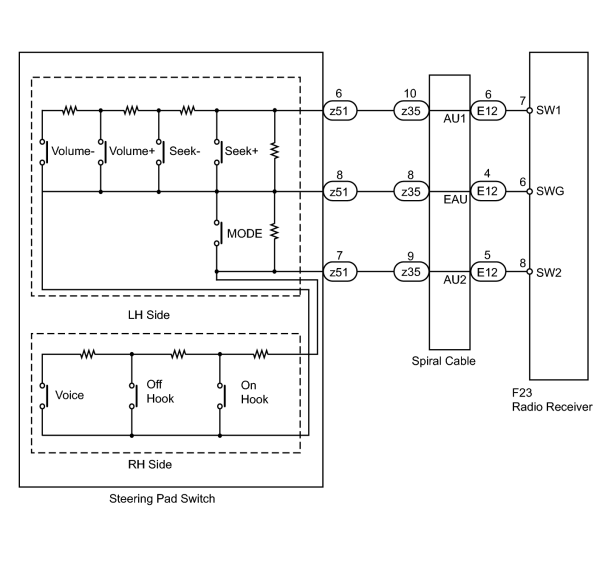
This circuit sends an operation signal from the steering pad switch to the radio receiver.
If there is an open in the circuit, the navigation system cannot be operated using the steering pad switch.
If there is a short in the circuit, the resulting condition is the same as if the switch were continuously depressed. Therefore, the navigation system cannot be operated using the steering pad switch, and the navigation system itself cannot function.
WIRING DIAGRAM
INSPECTION PROCEDURE
CAUTION:
The vehicle is equipped with an SRS (Supplemental Restraint System) which includes components such as airbags. Before servicing (including removal or installation of parts), be sure to read the Precaution for the SRS
 .
.
PROCEDURE
|
1. |
CHECK HARNESS AND CONNECTOR (RADIO RECEIVER - SPIRAL CABLE) |
|
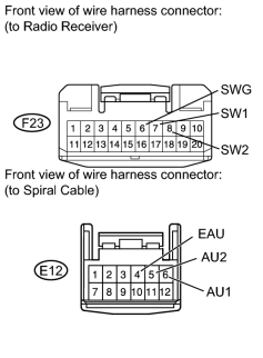
(a) Disconnect the F23 receiver connector. |
(b) Disconnect the E12 cable connector.
(c) Measure the resistance according to the value(s) in the table below.
Standard Resistance:
|
Tester Connection |
Condition |
Specified Condition |
|---|---|---|
|
F23-8 (SW2) - E12-5 (AU2) |
Always |
Below 1 Ω |
|
F23-6 (SWG) - E12-4 (EAU) |
||
|
F23-7 (SW1) - E12-6 (AU1) |
||
|
F23-8 (SW2) - Body ground |
Always |
10 kΩ or higher |
|
F23-6 (SWG) - Body ground |
||
|
F23-7 (SW1) - Body ground |
|

|
2. |
CHECK NO. 1 SWITCH WIRE |
|
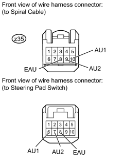
(a) Disconnect the z35 cable connector. |
(b) Disconnect the switch connector.
(c) Measure the resistance according to the value(s) in the table below.
Standard Resistance:
|
Tester Connection |
Condition |
Specified Condition |
|---|---|---|
|
z35-8 (EAU) - 8 (EAU) |
Always |
Below 1 Ω |
|
z35-9 (AU2) - 7 (AU2) |
||
|
z35-10 (AU1) - 6 (AU1) |
|
|
3. |
INSPECT SPIRAL CABLE SUB-ASSEMBLY |
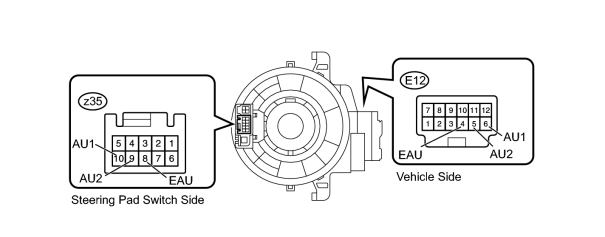
(a) Disconnect the z35 and E12 cable connectors.
(b) Measure the resistance according to the value(s) in the table below.
Standard Resistance:
|
Tester Connection |
Condition |
Specified Condition |
|---|---|---|
|
E12-4 (EAU) - z35-8 (EAU) |
Spiral cable is turned 2.5 rotations counterclockwise |
Below 3 Ω |
|
Spiral cable is centered |
||
|
Spiral cable is turned 2.5 rotations clockwise |
||
|
E12-5 (AU2) - z35-9 (AU2) |
Spiral cable is turned 2.5 rotations counterclockwise |
Below 3 Ω |
|
Spiral cable is centered |
||
|
Spiral cable is turned 2.5 rotations clockwise |
||
|
E12-6 (AU1) - z35-10 (AU1) |
Spiral cable is turned 2.5 rotations counterclockwise |
Below 3 Ω |
|
Spiral cable is centered |
||
|
Spiral cable is turned 2.5 rotations clockwise |
CAUTION:
The spiral cable is an important part of the SRS airbag system. Incorrect removal or installation of the spiral cable may prevent the airbag from deploying. Be sure to read the Precaution for the SRS
.
|
|
4. |
INSPECT STEERING PAD SWITCH |
(a) Disconnect the z51 switch connector.
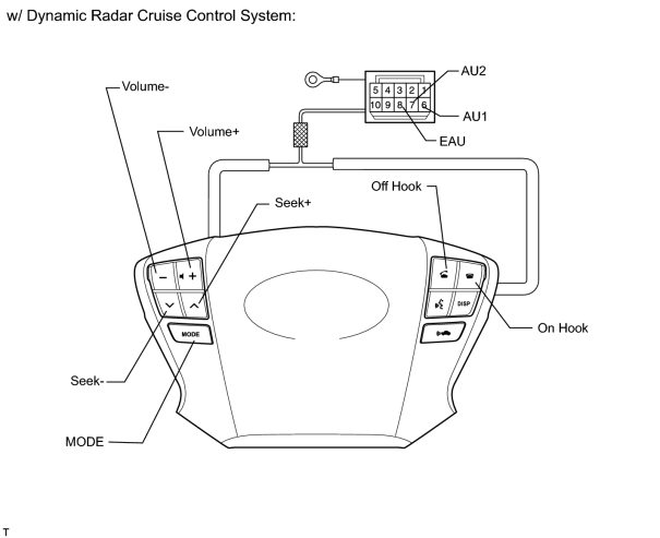
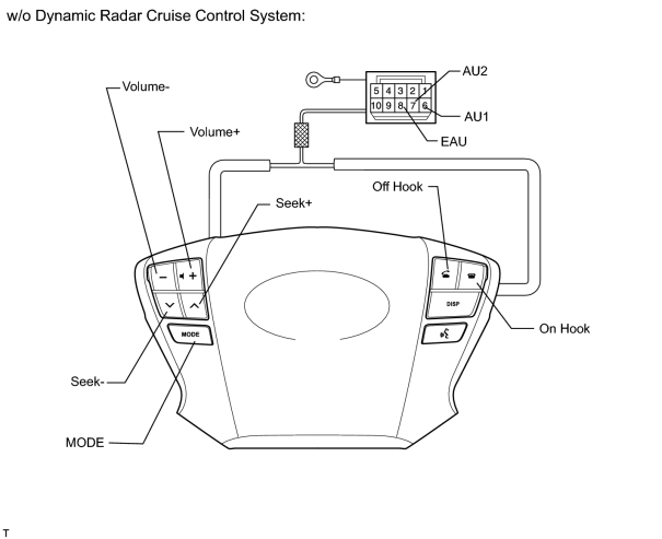
(b) Measure the resistance according to the value(s) in the table below.
Standard Resistance:
|
Tester Connection |
Switch Condition |
Specified Condition |
|---|---|---|
|
6 (AU1) - 8 (EAU) |
No switch is pushed |
100 kΩ |
|
6 (AU1) - 8 (EAU) |
Seek+ switch pushed |
Below 2.5 Ω |
|
6 (AU1) - 8 (EAU) |
Seek- switch pushed |
329 Ω |
|
6 (AU1) - 8 (EAU) |
Volume+ switch pushed |
1000 Ω |
|
6 (AU1) - 8 (EAU) |
Volume- switch pushed |
3110 Ω |
|
7 (AU2) - 8 (EAU) |
No switch is pushed |
100 kΩ |
|
7 (AU2) - 8 (EAU) |
MODE switch pushed |
Below 2.5 Ω |
|
7 (AU2) - 8 (EAU) |
On hook switch pushed |
329 Ω |
|
7 (AU2) - 8 (EAU) |
Off hook switch pushed |
1000 Ω |
|
7 (AU2) - 8 (EAU) |
Voice switch pushed |
3110 Ω |
|

|

|