- Open or short in speed signal circuit
- Combination meter
- ECM
| Last Modified: 11-27-2007 | 1.6 C | |
| Service Category: Engine/Hybrid System | Section: Engine Control | |
| Model Year: 2008 | Model: LX570 | Doc ID: RM0000012ME02SX |
| Title: 3UR-FE ENGINE CONTROL: SFI SYSTEM: DESCRIPTION (2008 LX570) | ||
|
DTC |
P0500 |
Vehicle Speed Sensor "A" |
DESCRIPTION
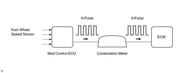
The speed sensor detects the wheel speed and sends the appropriate signals to the skid control ECU. The skid control ECU converts these wheel speed signals into a 4-pulse signal and outputs it to the ECM via the combination meter. The ECM determines the vehicle speed based on the frequency of these pulse signals.
|
DTC Code |
DTC Detection Condition |
Trouble Area |
|---|---|---|
|
P0500 |
While the vehicle is being driven, no vehicle speed sensor signal is transmitted to the ECM (2 trip detection logic). |
|
MONITOR DESCRIPTION
The ECM assumes that the vehicle is being driven when the indicated vehicle speed is more than 9 km/h (5.6 mph). If there is no speed signal from the combination meter despite these conditions being met, the ECM interprets this as a malfunction in the speed signal circuit. The ECM then illuminates the MIL and stores the DTC.
MONITOR STRATEGY
|
Related DTCs |
P0500: Vehicle speed sensor "A" pulse input error |
|
Required Sensors/Components (Main) |
Vehicle Speed Sensor (VSS), Combination meter and Skid control ECU |
|
Required Sensors/Components (Related) |
Park/Neutral Position (PNP) switch, Engine Coolant Temperature (ECT) sensor, Crankshaft Position (CKP) sensor, Throttle Position (TP) sensor and Mass Air Flow (MAF) meter |
|
Frequency of Operation |
Continuous |
|
Duration |
5 seconds |
|
MIL Operation |
2 driving cycles |
|
Sequence of Operation |
None |
TYPICAL ENABLING CONDITIONS
|
Monitor runs whenever following DTCs not stored |
P0120 - P0223, P2135 (TP sensor) |
|
Time after engine switch off to on (IG) |
3 seconds or more |
|
Transfer neutral switch |
Not "N" position |
|
Vehicle speed |
9 km/h (5.6 mph) or more |
|
Battery voltage |
8 V or higher |
|
Starter |
OFF |
TYPICAL MALFUNCTION THRESHOLDS
|
Vehicle speed sensor signal |
No pulse input |
WIRING DIAGRAM
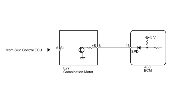
INSPECTION PROCEDURE
HINT:
Read freeze frame data using the Techstream. Freeze frame data records the engine condition when malfunctions are detected. When troubleshooting, freeze frame data can help determine if the vehicle was moving or stationary, if the engine was warmed up or not, if the air-fuel ratio was lean or rich, and other data from the time the malfunction occurred.
PROCEDURE
|
1. |
CHECK OPERATION OF SPEEDOMETER |
(a) Drive the vehicle and check whether the operation of the speedometer in the combination meter is normal.
HINT:
- The vehicle speed sensor is operating normally if the speedometer reading is normal.
-
If the speedometer does not operate, check it by following the procedure described in Speedometer Malfunction
 .
.
|

|
2. |
READ VALUE USING TECHSTREAM (VEHICLE SPD) |
(a) Connect the Techstream to the DLC3.
(b) Turn the engine switch on (IG).
(c) Turn the Techstream on.
(d) Enter the following menus: Powertrain / Engine and ECT / Data List / All Data / Vehicle Speed.
(e) Drive the vehicle.
(f) Read the value displayed on the Techstream.
OK:
Vehicle speeds displayed on Techstream and speedometer display are equal.
|
|
3. |
CHECK COMBINATION METER ASSEMBLY (+S VOLTAGE) |
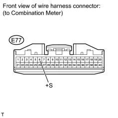
(a) Disconnect the E77 combination meter connector.
(b) Turn the engine switch on (IG).
(c) Measure the voltage according to the value(s) in the table below.
Standard Voltage:
|
Tester Connection |
Switch Condition |
Specified Condition |
|---|---|---|
|
E77-6 (+S) - Body ground |
Engine switch on (IG) |
4.5 to 5.5 V |
|
|
4. |
CHECK COMBINATION METER ASSEMBLY (SPD SIGNAL WAVEFORM) |
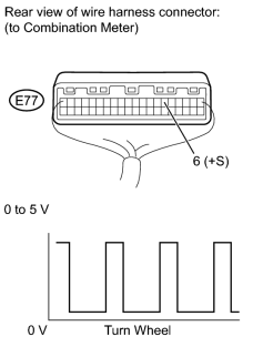
(a) Move the shift lever to N.
(b) Jack up the vehicle.
(c) Turn the engine switch on (IG).
(d) Measure the voltage according to the value(s) in the table below.
Standard Voltage:
|
Tester Connection |
Switch Condition |
Specified Condition |
|---|---|---|
|
E77-6 (+S) - Body ground |
|
Voltage generated intermittently |
HINT:
The output voltage should fluctuate up and down, similarly to the diagram, when the wheel is turned slowly.
|
|
5. |
CHECK HARNESS AND CONNECTOR (COMBINATION METER - ECM) |
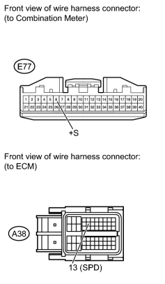
(a) Disconnect the E77 combination meter connector.
(b) Disconnect the A38 ECM connector.
(c) Measure the resistance according to the value(s) in the table below.
Standard Resistance:
|
Tester Connection |
Condition |
Specified Condition |
|---|---|---|
|
E77-6 (+S) - A38-13 (SPD) |
Always |
Below 1 Ω |
|
E77-6 (+S) or A38-13 (SPD) - Body ground |
Always |
10 kΩ or higher |
|

|

|