- ATF temperature warning indicator remains on
- Shift point too high
| Last Modified: 11-27-2007 | 1.6 C | |
| Service Category: Drivetrain | Section: Automatic Transmission/Transaxle | |
| Model Year: 2008 | Model: LX570 | Doc ID: RM0000012XR01WX |
| Title: AB60F AUTOMATIC TRANSMISSION / TRANSAXLE: AUTOMATIC TRANSMISSION SYSTEM: DESCRIPTION (2008 LX570) | ||
|
DTC |
P2740 |
Transmission Fluid Temperature Sensor "B" Circuit |
|
DTC |
P2742 |
Transmission Fluid Temperature Sensor "B" Circuit Low Input |
|
DTC |
P2743 |
Transmission Fluid Temperature Sensor "B" Circuit High Input |
DESCRIPTION
The Automatic Transmission Fluid (ATF) temperature sensor is on the transmission, just in front of the oil cooler inlet pipeline.
If the ECM detects an abnormally high ATF temperature near this sensor, it illuminates the warning light.
HINT:
- The temperature of ATF easily rises when towing, climbing hills, in traffic, etc.
- If the ATF temperature sensor becomes short-circuited, the signal that indicates that the ATF temperature is 150°C (302°F) or higher is input into the ECM.
Vehicle conditions when the sensor is normal and when the sensor is short-circuited are indicated in the table below.
|
No. 2 ATF Temperature Sensor State |
Detection Condition |
Symptom |
Recovery Condition |
|---|---|---|---|
|
Sensor is normal |
ATF temperature higher than 150°C (302°F) |
ATF temperature warning indicator remains on |
ATF temperature below 135°C (275°F)*1 |
|
ATF temperature higher than 130°C (266°F) |
Shift point too high |
ATF temperature below 110°C (230°F) |
|
|
When conditions (a) and (b) are satisfied: (a) ATF temperature higher than 130°C (266°F) (b) Engine coolant temperature higher than 95°C (203°F) |
Lock-up at 3rd gear*2 |
ATF temperature below 110°C (230°F)*1 and engine coolant temperature higher than 95°C (203°F) |
|
|
Sensor is short-circuited |
Any conditions |
|
Symptoms still occur |
|
Engine coolant temperature higher than 95°C (203°F) |
Lock-up at 3rd gear*2 |
Symptoms still occur |
HINT:
*1: When ATF temperature is in the normal range, it decreases to below 135°C (275°F) within 5 minutes with the shift lever in P or N in an idling state.
*2: When ATF temperature is normal, transmission lock-up occurs in 5th or 6th gear with the shift lever in D or the S6 range, in 5th gear with the shift lever in the S5 range, and 4th gear with the shift lever in the S4 range.
|
DTC Code |
DTC Detection Condition |
Trouble Area |
|---|---|---|
|
P2740 |
(a) and (b) are detected momentarily within 0.5 sec. when neither P2742 nor P2743 are stored (1-trip detection logic). (a) The No. 2 ATF temperature sensor resistance is below 25 Ω (0.046 V). (b) The No. 2 ATF temperature sensor resistance is higher than 156 kΩ (4.915 V). HINT: Within 0.5 sec., the malfunction switches from (a) to (b) or from (b) to (a). |
|
|
P2742 |
The No. 2 ATF temperature sensor resistance is below 25 Ω (0.046 V) for 0.5 sec. or more (1-trip detection logic). |
|
|
P2743 |
When 15 min. or more have elapsed after the engine is started, the No. 2 ATF temperature sensor resistance is higher than 156 kΩ (4.915 V) for 0.5 sec. or more (1-trip detection logic). |
|
MONITOR DESCRIPTION
The ATF temperature sensor converts the ATF temperature into an electrical resistance value. Based on the resistance, the ECM determines the ATF temperature, and the ECM detects an open or short in the ATF temperature circuit. If the resistance value of the ATF temperature is below 25 Ω*1 or higher than 156 kΩ*2, the ECM interprets this as a fault in the ATF sensor or wiring. The ECM will illuminate the MIL and store the DTC.
HINT:
- *1: 150°C (302°F) or higher is indicated regardless of the actual ATF temperature.
- *2: -40°C (-40°F) is indicated regardless of the actual ATF temperature.
- The ATF temperature can be checked on the Techstream display.
MONITOR STRATEGY
|
Related DTCs |
P2740: ATF temperature sensor/Range check (Fluttering) P2742: ATF temperature sensor/Range check (Low resistance) P2743: ATF temperature sensor/Range check (High resistance) |
|
Required sensors/Components |
ATF temperature sensor |
|
Frequency of operation |
Continuous |
|
Duration |
0.5 sec. |
|
MIL operation |
Immediately |
|
Sequence of operation |
None |
TYPICAL ENABLING CONDITIONS
All
|
The monitor will run whenever the following DTCs are not stored |
None |
P2740, P2742: Range Check (Chattering, Low Voltage)
|
The typical enabling condition is not available. |
- |
P2743: Range Check (High Voltage)
|
Time after engine start |
15 min. or more |
TYPICAL MALFUNCTION THRESHOLDS
P2740: Range Check (Chattering)
|
ATF temperature sensor voltage |
Below 0.046 V or higher than 4.915 V |
P2742: Range Check (Low Voltage)
|
ATF temperature sensor voltage |
Below 0.046 V |
P2743: Range Check (High Voltage)
|
ATF temperature sensor voltage |
Higher than 4.915 V |
COMPONENT OPERATING RANGE
|
ATF temperature sensor voltage |
0.046 to 4.915 V |
WIRING DIAGRAM
Refer to DTC P0710
 .
.
INSPECTION PROCEDURE
1. DATA LIST
HINT:
Using the Techstream to read the Data List allows the values or states of switches, sensors, actuators and other items to be read without removing any parts. This non-intrusive inspection can be very useful because intermittent conditions or signals may be discovered before parts or wiring is disturbed. Reading the Data List information early in troubleshooting is one way to save diagnostic time.
NOTICE:
In the table below, the values listed under "Normal Condition" are reference values. Do not depend solely on these reference values when deciding whether a part is faulty or not.
(a) Warm up the engine.
(b) Turn the engine switch off.
(c) Connect the Techstream to the DLC3.
(d) Turn the engine switch on (IG).
(e) Turn the Techstream on.
(f) Enter the following menus: Powertrain / Engine and ECT / Data List.
(g) According to the display on the Techstream, read the Data List.
Engine and ECT
|
Tester Display |
Measurement Item/Range |
Normal Condition |
Diagnostic Note |
|---|---|---|---|
|
A/T Oil Temperature 2 |
No. 2 ATF temperature sensor value/ Min.: -40°C (-40°F) Max.: 215°C (419°F) |
|
If the value is -40°C (-40°F) or 215°C (419°F), the No. 2 ATF temperature sensor circuit is open or shorted. |
HINT:
- When DTC P2742 is stored and the Techstream output is 150°C (302°F) or higher, there is a short circuit.
-
When DTC P2743 is stored and the Techstream output is -40°C (-40°F), there is an open circuit.
Check the temperature displayed on the Techstream in order to check if a malfunction exists.
|
Temperature Displayed |
Malfunction |
|---|---|
|
-40°C (-40°F) |
Open circuit |
|
150°C (302°F) or higher |
Short circuit |
PROCEDURE
|
1. |
INSPECT NO. 1 TRANSMISSION WIRE (NO. 2 ATF TEMPERATURE SENSOR) |
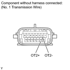
|
(a) Disconnect the C39 No. 1 transmission wire connector. |
(b) Measure the resistance according to the value(s) in the table below.
Standard Resistance:
|
Tester Connection |
Condition |
Specified Condition |
|---|---|---|
|
10 (OT2+) - 2 (OT2-) |
Always |
25 Ω to 156 kΩ |
|
10 (OT2+) - Body ground |
Always |
10 kΩ or higher |
|
2 (OT2-) - Body ground |
Always |
10 kΩ or higher |
HINT:
If the resistance is out of the specified range at one of the ATF temperatures shown in the table below, the driveability of the vehicle may decrease.
Resistance (Reference):
|
ATF Temperature |
Specified Condition |
|---|---|
|
10°C (50°F) |
5 to 8 kΩ |
|
25°C (77°F) |
2.5 to 4.5 kΩ |
|
110°C (230°F) |
0.22 to 0.28 kΩ |
|

|
2. |
CHECK HARNESS AND CONNECTOR (NO. 1 TRANSMISSION WIRE - ECM) |
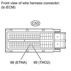
|
(a) Disconnect the C53 ECM connector. |
(b) Measure the resistance according to the value(s) in the table below.
Standard Resistance:
|
Tester Connection |
Condition |
Specified Condition |
|---|---|---|
|
C53-99 (THO2) - C53-98 (ETHA) |
Always |
25 Ω to 156 kΩ |
|
C53-99 (THO2) - Body ground |
Always |
10 kΩ or higher |
|
C53-98 (ETHA) - Body ground |
Always |
10 kΩ or higher |
|

|

|