| Last Modified: 11-27-2007 | 1.6 A | |
| Service Category: Drivetrain | Section: Automatic Transmission/Transaxle | |
| Model Year: 2008 | Model: LX570 | Doc ID: RM0000013F001HX |
| Title: AB60F AUTOMATIC TRANSMISSION / TRANSAXLE: AUTOMATIC TRANSMISSION UNIT: REASSEMBLY (2008 LX570) | ||
REASSEMBLY
1. BEARING POSITION
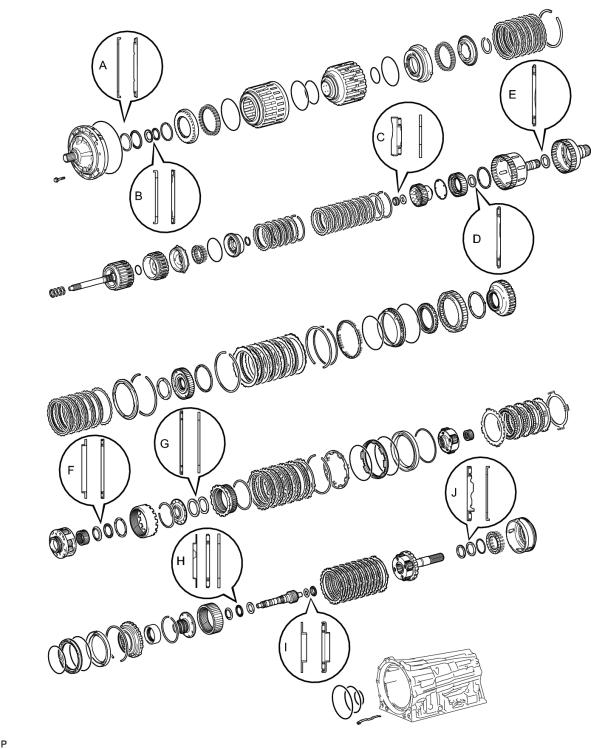
Bearing and Race Diameter:
|
Mark |
Front Race Diameter Inside / Outside |
Thrust Bearing Diameter Inside / Outside |
Rear Race Diameter Inside / Outside |
|---|---|---|---|
|
A |
74.26 to 74.56 mm (2.92 to 2.94 in.) / 87.39 to 87.74 mm (3.44 to 3.45 in.) |
71.96 to 72.26 mm (2.83 to 2.84 in.) / 85.25 to 85.6 mm (3.36 to 3.37 in.) |
- |
|
B |
38.0 to 38.3 mm (1.50 to 1.51 in.) / 53.9 to 54.1 mm (2.12 to 2.13 in.) |
36.45 to 36.7 mm (1.44 to 1.45 in.) / 52.96 to 53.26 mm (2.09 to 2.10 in.) |
- |
|
C |
- |
21.05 to 21.3 mm (0.829 to 0.839 in.) / 39.63 to 39.88 mm (1.56 to 1.57 in.) |
22.8 to 23.1 mm (0.898 to 0.909 in.) / 44.5 to 44.75 mm (1.75 to 1.76 in.) |
|
D |
- |
39.45 to 39.7 mm (1.55 to 1.56 in.) / 60.5 to 60.75 mm (2.38 to 2.39 in.) |
- |
|
E |
- |
46.45 to 46.7 mm (1.83 to 1.84 in.) / 64.3 to 64.55 mm (2.53 to 2.54 in.) |
- |
|
F |
55.0 to 55.2 mm (2.165 to 2.173 in.) / 68.8 to 69.3 mm (2.71 to 2.73 in.) |
54.55 to 54.8 mm (2.15 to 2.16 in.) / 70.0 to 70.5 mm (2.76 to 2.78 in.) |
- |
|
G |
- |
65.35 to 65.6 mm (2.57 to 2.58 in.) / 85.6 to 85.95 mm (3.37 to 3.38 in.) |
62.85 to 63.1 mm (2.47 to 2.48 in.) / 82.3 to 82.6 mm (3.24 to 3.25 in.) |
|
H |
39.67 to 39.87 mm (1.56 to 1.57 in.) / 56.5 to 57.0 mm (2.22 to 2.24 in.) |
36.5 to 36.6 mm (1.437 to 1.441 in.) / 56.62 to 56.92 mm (2.23 to 2.24 in.) |
36.45 to 36.7 mm (1.435 to 1.445 in.) / 56.5 to 57.0 mm (2.22 to 2.24 in.) |
|
I |
21.05 to 21.3 mm (0.829 to 0.839 in.) / 39.5 to 39.8 mm (1.56 to 1.57 in.) |
23.2 to 23.4 mm (0.913 to 0.921 in.) / 43.9 to 44.15 mm (1.73 to 1.74 in.) |
- |
|
J |
- |
43.6 to 43.9 mm (1.72 to 1.73 in.) / 62.3 to 62.8 mm (2.45 to 2.47 in.) |
47.15 to 47.4 mm (1.86 to 1.87 in.) / 66.9 to 67.1 mm (2.63 to 2.64 in.) |
2. INSTALL 1ST AND REVERSE BRAKE PISTON
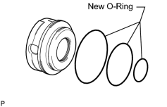
(a) Coat 3 new O-rings with ATF, and install them to the 1st and reverse brake piston.
|
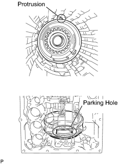
(b) Install the 1st and reverse brake piston to the transmission case. NOTICE:
|
3. INSTALL 1ST AND REVERSE BRAKE RETURN SPRING SUB-ASSEMBLY
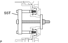
(a) Place the brake return spring onto the 1st and reverse brake piston.
SST: 09380-60010
09381-06030
09381-06040
09381-06080
09381-06120
09381-06130
09381-05040
09381-05050
(b) Place SST on the spring retainer, and compress the return spring.
(c) Using SST, install the snap ring.
SST: 09350-30020
09350-07070
4. SELECT NO. 4 BRAKE FLANGE
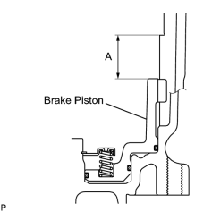
(a) Measure distance A (from the tip of the 1st and reverse brake piston to the step in the transmission case) in the illustration.*1
HINT:
Standard distance A: 27.82 to 28.42 mm (1.09 to 1.12 in.)
|
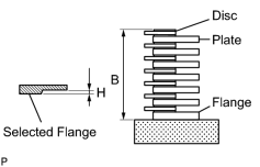
(b) Assemble the No. 4 brake flange, 7 No. 4 brake discs and 6 No. 4 brake plates, and measure distance B in the illustration.*2 HINT:
Standard distance B: 25.98 to 27.01 mm (1.02 to 1.06 in.) |
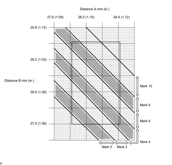
(c) Apply the A and B measurements taken in *1 and *2 to the graph below. Use A for the X axis and B for the Y axis, and then choose the No. 4 brake selective flange indicated by the graph point.
(d) Measure length H of the selected flange as shown in the illustration.
HINT:
Make sure that when the B measurement and H dimension of the selected flange are subtracted from the A measurement, the value is 0.961 to 1.261 mm (0.0378 to 0.0495 in.).
No. 4 Brake Selected Flange Length H:
|
Mark |
Length H |
|---|---|
|
0 |
0 mm (0 in.) |
|
2 |
0.15 to 0.25 mm (0.00590 to 0.00984 in.) |
|
4 |
0.35 to 0.45 mm (0.0138 to 0.0177 in.) |
|
6 |
0.55 to 0.65 mm (0.0217 to 0.0256 in.) |
|
8 |
0.75 to 0.85 mm (0.0295 to 0.0335 in.) |
|
10 |
0.95 to 1.05 mm (0.0374 to 0.0413 in.) |
5. INSTALL REAR PLANETARY GEAR ASSEMBLY
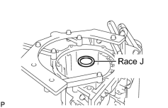
(a) Install the thrust bearing race.
HINT:
Use a small amount of MP grease to make the thrust bearing race stay securely in place.
Bearing Race Diameter:
|
Item |
Inside |
Outside |
|---|---|---|
|
Race J |
47.15 to 47.4 mm (1.86 to 1.87 in.) |
66.9 to 67.1 mm (2.63 to 2.64 in.) |
|
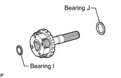
(b) Install the 2 thrust needle roller bearings to the rear planetary gear. Bearing Diameter:
HINT:
Use a small amount of MP grease to make the thrust needle roller bearings stay securely in place. |
|
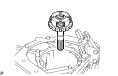
(c) Install the rear planetary gear assembly. |
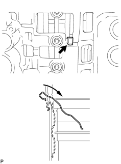
6. INSTALL BRAKE PLATE STOPPER SPRING
7. INSTALL REAR PLANETARY RING GEAR
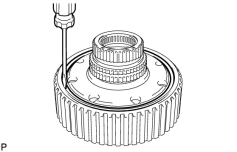
(a) Install the rear planetary ring gear flange to the rear planetary ring gear.
(b) Using a screwdriver, install the snap ring.
|
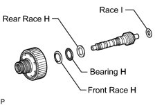
(c) Install the 3 thrust bearing races, thrust needle roller bearing and planetary ring gear with the rear planetary ring gear flange to the intermediate shaft. HINT:
Use a small amount of MP grease to make the thrust needle roller bearing and races stay securely in place. Bearing and Race Diameter:
|
8. INSTALL INTERMEDIATE SHAFT WITH REAR PLANETARY RING GEAR FLANGE AND REAR PLANETARY RING GEAR
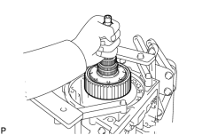
(a) Install the intermediate shaft with the rear planetary ring gear flange and rear planetary ring gear to the transmission case.
9. INSTALL NO. 4 BRAKE DISC SET
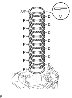
(a) Install the flange, 7 discs, 6 plates and selected flange.
Install in order:
F - D - P - D - P - D - P - D - P - D - P - D - P - D - S/F
HINT:
F = Flange
D = Disc
P = Plate
S/F = Selected flange
NOTICE:
Before assembling new discs, soak them in ATF for at least 2 hours.
10. INSTALL NO. 3 1-WAY CLUTCH INNER RACE
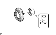
(a) Install the 1-way clutch inner race to the No. 3 1-way clutch assembly.
NOTICE:
Do not mistake the direction of the 1-way clutch inner race.
11. INSPECT NO. 3 1-WAY CLUTCH ASSEMBLY

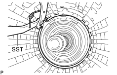
12. INSTALL NO. 3 1-WAY CLUTCH ASSEMBLY
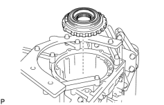
(a) Install the 1-way clutch assembly to the transmission case.
|
(b) Using SST, install the snap ring. SST: 09350-30020 09350-07060 |
13. INSTALL NO. 2 BRAKE PISTON
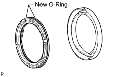
(a) Coat 2 new O-rings with ATF, and install them to the brake piston.
(b) Press the brake piston into the brake cylinder with both hands.
NOTICE:
Be careful not to damage the O-rings.
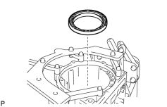
14. INSTALL NO. 2 BRAKE CYLINDER WITH NO. 2 BRAKE PISTON
|
(a) Install the No. 2 brake cylinder with piston to the transmission case. NOTICE:
|
15. SELECT NO. 2 BRAKE FLANGE
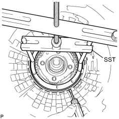
(a) Install the No. 2 brake piston return spring and flange to the No. 2 brake piston.
(b) Place SST on the brake flange and compress the brake return spring.
SST: 09380-60010
09381-06010
09381-06020
09381-06050
09381-06070
09381-06090
09381-06120
(c) Using a screwdriver, install the snap ring to the transmission case.
|
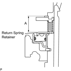
(d) Measure distance A (from the top surface of the snap ring to the top surface of the brake piston return spring retainer) in the illustration.*1 HINT:
Standard distance A: 21.00 to 21.76 mm (0.834 to 0.857 in.) |
|
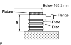
(e) Assemble the 4 discs, 3 plates and flange as shown in the illustration. Then with a fixture of 165.2 mm (6.50 in.) or less placed on the flange, measure distance B.*2 HINT:
Standard distance B: 16.54 to 17.15 mm (0.651 to 0.675 in.) |
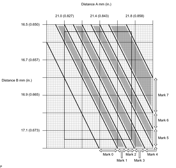
(f) Apply the A and B measurements taken in *1 and *2 to the graph below. Use A for the X axis and B for the Y axis, and then choose the flange indicated by the graph point.
HINT:
Make sure that when the B measurement and selected flange thickness are subtracted from the A measurement, the value is 2.20 to 2.50 mm (0.0866 to 0.0984 in.).
Flange Thickness:
|
Mark |
Thickness |
|---|---|
|
0 |
1.95 to 2.05 mm (0.0768 to 0.0807 in.) |
|
1 |
2.05 to 2.15 mm (0.0807 to 0.0846 in.) |
|
2 |
2.15 to 2.25 mm (0.0846 to 0.0886 in.) |
|
3 |
2.25 to 2.35 mm (0.0886 to 0.0925 in.) |
|
4 |
2.35 to 2.45 mm (0.0925 to 0.0965 in.) |
|
5 |
2.45 to 2.55 mm (0.0965 to 0.100 in.) |
|
6 |
2.55 to 2.65 mm (0.100 to 0.104 in.) |
|
7 |
2.65 to 2.75 mm (0.104 to 0.108 in.) |
(g) Remove the snap ring, flange and No. 2 brake piston return spring from the transmission case.
16. INSTALL NO. 2 BRAKE DISC SET
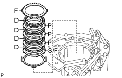
(a) Install the brake piston return spring, selected flange, 4 discs, 3 plates and flange.
Install in order:
S/F - D - P - D - P - D - P - D - F
HINT:
S/F = Selected flange
D = Disc
P = Plate
F = Flange
NOTICE:
Before assembling new discs, soak them in ATF for at least 2 hours.
|
|
(b) Place SST on the brake flange and compress the brake return spring. SST: 09380-60010 09381-06010 09381-06020 09381-06050 09381-06070 09381-06090 09381-06120 |
(c) Using a screwdriver, install the snap ring to the transmission case.
17. INSTALL CENTER PLANETARY GEAR ASSEMBLY
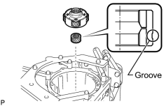
(a) Install the center planetary sun gear and center planetary gear to the transmission case.
NOTICE:
Make sure to install the center planetary sun gear with the groove facing the transmission case.
18. INSTALL NO. 1 BRAKE PISTON
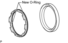
(a) Coat 2 new O-rings with ATF, and install them to the brake piston.
(b) Press the brake piston into the brake cylinder with both hands.
NOTICE:
Be careful not to damage the O-rings.
19. INSTALL NO. 1 BRAKE CYLINDER WITH NO. 1 BRAKE PISTON
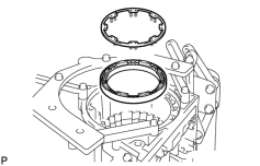
|
(a) Install the No. 1 brake cylinder with piston and brake piston return spring to the transmission case. NOTICE:
|
|
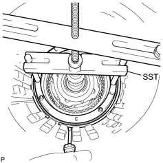
(b) Place SST on the brake return spring and compress the brake return spring. SST: 09380-60010 09381-06010 09381-06020 09381-06050 09381-06060 09381-06090 09381-06100 09381-06110 09381-06120 |
(c) Using a screwdriver, install the snap ring to the transmission case.
20. SELECT NO. 1 BRAKE FLANGE
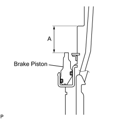
(a) Measure distance A (from the step in the transmission case to the tip of the No. 1 brake piston) in the illustration.*1
HINT:
Standard distance A: 19.74 to 20.22 mm (0.777 to 0.796 in.)
|
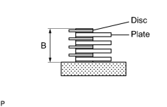
(b) Assemble the 4 plates and 4 discs and measure distance B in the illustration.*2 HINT:
Standard distance B: 16.72 to 17.19 mm (0.658 to 0.677 in.) |
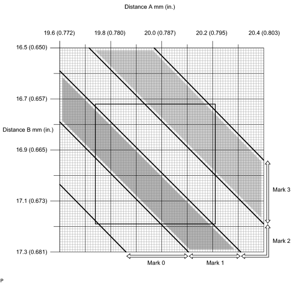
(c) Apply the A and B measurements taken in *1 and *2 to the graph below. Use A for the X axis and B for the Y axis, and then choose the flange indicated by the graph point.
HINT:
Make sure that when the B measurement and selected flange thickness are subtracted from the A measurement, the value is 0.56 to 0.86 mm (0.0220 to 0.0339 in.).
Flange Thickness:
|
Mark |
Thickness |
|---|---|
|
0 |
1.95 to 2.05 mm (0.0768 to 0.0807 in.) |
|
1 |
2.15 to 2.25 mm (0.0846 to 0.0886 in.) |
|
2 |
2.35 to 2.45 mm (0.0925 to 0.0965 in.) |
|
3 |
2.55 to 2.65 mm (0.100 to 0.104 in.) |
21. INSTALL CENTER PLANETARY RING GEAR
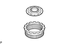
(a) Install the front planetary ring gear flange to the center planetary ring gear.
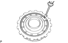
|
(b) Using a screwdriver, install the snap ring. |
22. INSTALL FRONT PLANETARY RING GEAR
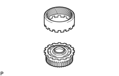
(a) Install the front planetary ring gear to the center planetary ring gear.
23. INSTALL FRONT PLANETARY RING GEAR WITH FRONT PLANETARY RING GEAR FLANGE SUB-ASSEMBLY AND CENTER PLANETARY RING GEAR
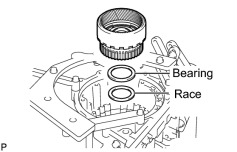
(a) Install the thrust bearing race and thrust needle roller bearing.
HINT:
Use a small amount of MP grease to make the thrust needle roller bearing and race stay securely in place.
Bearing and Race Diameter:
|
Item |
Inside |
Outside |
|---|---|---|
|
Race |
62.85 to 63.1 mm (2.47 to 2.48 in.) |
82.3 to 82.6 mm (3.24 to 3.25 in.) |
|
Bearing |
65.35 to 65.6 mm (2.57 to 2.58 in.) |
85.6 to 85.95 mm (3.37 to 3.38 in.) |
(b) Install the front planetary ring gear with the front planetary ring gear flange and center planetary ring gear to the transmission case.
24. INSTALL FRONT PLANETARY GEAR ASSEMBLY
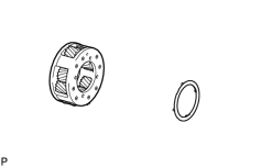
(a) Install the No. 2 planetary carrier thrust washer to the front planetary gear.
HINT:
Use a small amount of MP grease to make the thrust washer stay securely in place.
|
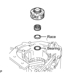
(b) Install the thrust needle roller bearing, thrust bearing race, front planetary sun gear and front planetary gear. HINT:
Use a small amount of MP grease to make the thrust needle roller bearing and race stay securely in place. Bearing Diameter:
|
25. INSTALL 1-WAY CLUTCH INNER RACE SUB-ASSEMBLY
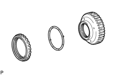
(a) Apply the No. 1 planetary carrier thrust washer to the 1-way clutch inner race, and then install them to the 1-way clutch.
HINT:
Use a small amount of MP grease to make the thrust washer stay securely in place.
26. INSPECT 1-WAY CLUTCH ASSEMBLY
27. INSTALL 1-WAY CLUTCH ASSEMBLY WITH 1-WAY CLUTCH INNER RACE SUB-ASSEMBLY
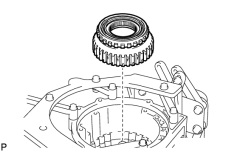
(a) Install the 1-way clutch with the 1-way clutch inner race to the transmission case.
28. INSTALL NO. 1 BRAKE DISC SET
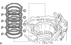
(a) Install the 4 plates, 4 discs and flange.
Install in order:
P - D - P - D - P - D - P - D - F
HINT:
P = Plate
D = Disc
F = Flange
NOTICE:
Before assembling new discs, soak them in ATF for at least 2 hours.
29. INSTALL NO. 3 BRAKE PISTON
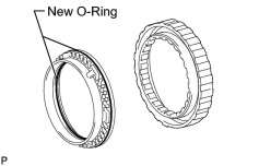
(a) Coat 2 new O-rings with ATF, and install them to the brake piston.
(b) Press the brake piston into the brake cylinder with both hands.
NOTICE:
Be careful not to damage the O-rings.
|
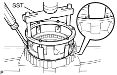
(c) Using SST and a press, compress the return spring and install the snap ring with a screwdriver. SST: 09380-60010 09381-06020 09381-06040 09381-06060 09381-06100 09381-06110 NOTICE:
Be sure the end gap of the snap ring is not aligned with the spring retainer claw. |
30. INSTALL NO. 3 BRAKE CYLINDER WITH NO. 3 BRAKE PISTON AND NO. 3 BRAKE PISTON RETURN SPRING SUB-ASSEMBLY
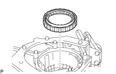
(a) Install the No. 3 brake cylinder with the No. 3 brake piston and No. 3 brake piston return spring to the transmission case.
NOTICE:
-
Align the oil holes of the No. 3 brake cylinder and transmission case as shown in the illustration.
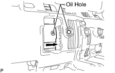
- Make sure the No. 3 brake piston and cylinder are securely inserted into the transmission case.
31. INSTALL NO. 3 BRAKE PISTON HOLE SNAP RING
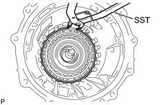
(a) Using SST, install the snap ring.
SST: 09350-30020
09350-07060
32. INSTALL NO. 3 BRAKE DISC SET
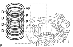
(a) Install the "O" mark flange, 4 discs, 3 plates and "A" mark flange to the transmission case.
Install in order:
OF - D - P - D - P - D - P - D - AF
HINT:
OF = "O" mark flange
P = Plate
D = Disc
AF = "A" mark flange
NOTICE:
Before assembling new discs, soak them in ATF for at least 2 hours.
33. INSTALL NO. 3 BRAKE SNAP RING
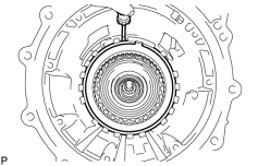
(a) Using a screwdriver, install the snap ring.
34. INSTALL DIRECT CLUTCH PISTON SUB-ASSEMBLY
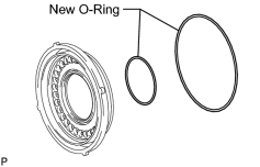
(a) Coat 2 new O-rings with ATF, and install them to the direct clutch piston.
|
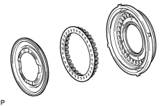
(b) Install the direct clutch return spring and No. 2 clutch balancer to the direct clutch piston. |
|
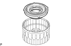
(c) Press the direct clutch piston with the clutch return spring and clutch balancer into the reverse clutch piston with both hands. NOTICE:
Be careful not to damage the O-ring. |
|
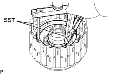
(d) Place SST on the direct clutch balancer, and compress the return spring with a press. SST: 09380-60010 09381-06030 09381-06040 09381-06080 NOTICE:
Stop pressing when the spring sheet is lowered to a position 1 to 2 mm (0.0394 to 0.0787 in.) from the snap ring groove to prevent the spring sheet from being deformed. |
(e) Using SST, install the snap ring.
SST: 09350-30020
09350-07070
NOTICE:
Do not expand the snap ring excessively.
|
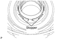
(f) Set the end gap of the snap ring in the balancer as shown in the illustration. NOTICE:
Be sure the end gap of the snap ring is not aligned with the spring retainer claw. |
35. INSTALL REVERSE CLUTCH PISTON SUB-ASSEMBLY
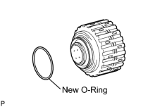
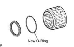
(a) Coat a new O-ring with ATF, and install it to the clutch drum.
|
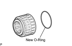
(b) Coat a new O-ring with ATF, and install it to the reverse clutch piston. |
|
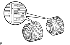
(c) Pass the clutch drum into the reverse clutch piston with both hands. NOTICE:
|
36. INSTALL NO. 3 CLUTCH BALANCER
(a) Coat a new O-ring with ATF, and install it to the reverse clutch piston.
(b) Install the reverse clutch return spring and balancer onto the reverse clutch piston.
|
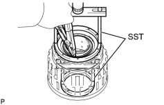
(c) Place SST on the clutch balancer, and compress the clutch balancer with a press. SST: 09380-60010 09381-06020 09381-06030 09381-06040 09381-06050 09381-06070 09381-06080 NOTICE:
Stop pressing when the spring sheet is lowered to a position 1 to 2 mm (0.0394 to 0.0787 in.) from the snap ring groove to prevent the spring sheet from being deformed. |
(d) Using SST, install the snap ring.
SST: 09350-30020
09350-07070
NOTICE:
Do not expand the snap ring excessively.
|
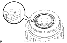
(e) Set the end gap of the snap ring in the piston as shown in the illustration. NOTICE:
Be sure the end gap of the snap ring is not aligned with the spring retainer claw. |
37. INSTALL DIRECT CLUTCH DISC
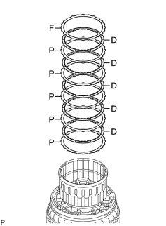
(a) Place the oil pump onto the torque converter clutch, and then place the clutch drum onto the oil pump.
(b) Install the 5 plates, 5 discs and reverse clutch flange to the clutch drum.
Install in order:
P - D - P - D - P - D - P - D - P - D - F
HINT:
P = Plate
D = Disc
F = Flange
NOTICE:
Before assembling new discs, soak them in ATF for at least 2 hours.
|
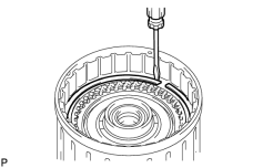
(c) Using a screwdriver, install the snap ring to the clutch drum. |
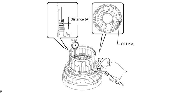
(d) Using a dial indicator, measure the moving distance (A) of the clutch flange at both ends across the diameter while blowing compressed air (392 kPa, 2.0 kgf/cm2, 57 psi) into the oil hole as shown in the illustration. Then choose from the 9 flange thicknesses in the table so that the measured value is within the standard value.
Standard moving distance (A):
0.58 to 0.88 mm (0.0228 to 0.0346 in.)
Flange Thickness:
|
Mark |
Thickness |
|---|---|
|
0 |
3.45 to 3.55 mm (0.136 to 0.140 in.) |
|
1 |
3.55 to 3.65 mm (0.140 to 0.144 in.) |
|
2 |
3.65 to 3.75 mm (0.144 to 0.148 in.) |
|
3 |
3.75 to 3.85 mm (0.148 to 0.152 in.) |
|
4 |
3.85 to 3.95 mm (0.152 to 0.156 in.) |
|
5 |
3.95 to 4.05 mm (0.156 to 0.159 in.) |
|
6 |
4.05 to 4.15 mm (0.159 to 0.163 in.) |
|
7 |
4.15 to 4.25 mm (0.163 to 0.167 in.) |
|
8 |
4.25 to 4.35 mm (0.167 to 0.171 in.) |
(e) Temporarily remove the snap ring, install the selected flange and reinstall the snap ring.
38. SELECT REVERSE CLUTCH FLANGE
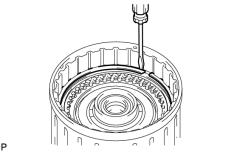
(a) Using a screwdriver, install the snap ring to the clutch drum.
NOTICE:
Make sure to install the direct clutch and reverse clutch snap rings so that their openings face opposite directions.
|
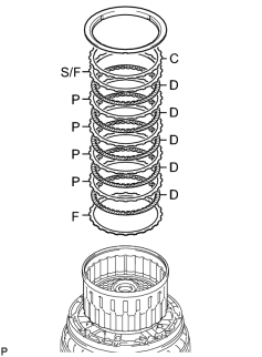
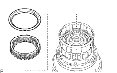
(b) Install the flange, 5 discs, 4 plates, selected flange, cushion plate and reverse clutch reaction sleeve to the clutch drum. Install in order: F - D - P - D - P - D - P - D - P - D - S/F - C HINT:
F = Flange HINT: D = Disc HINT: P = Plate HINT: S/F = Selected flange HINT: C = Cushion plate |

|
(c) Using a screwdriver, install the hole snap ring. |
(d) Using a dial indicator, measure the moving distance (A minus B) of the tip of the reverse clutch piston (A) and cushion plate at both ends across the diameter (B) while blowing compressed air (392 kPa, 2.0 kgf/cm2, 57 psi) into the oil hole as shown in the illustration. Then choose from the 12 flange thicknesses in the table so that the measured value is within the standard value.
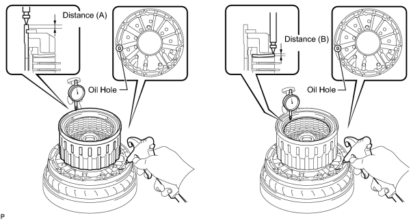
Standard moving distance (A minus B):
0.59 to 0.89 mm (0.0232 to 0.0350 in.)
Flange Thickness:
|
Mark |
Thickness |
|---|---|
|
0 |
2.35 to 2.45 mm (0.0925 to 0.0965 in.) |
|
1 |
2.45 to 2.55 mm (0.0965 to 0.100 in.) |
|
2 |
2.55 to 2.65 mm (0.100 to 0.104 in.) |
|
3 |
2.65 to 2.75 mm (0.104 to 0.108 in.) |
|
4 |
2.75 to 2.85 mm (0.108 to 0.112 in.) |
|
5 |
2.85 to 2.95 mm (0.112 to 0.116 in.) |
|
6 |
2.95 to 3.05 mm (0.116 to 0.120 in.) |
|
7 |
3.05 to 3.15 mm (0.120 to 0.124 in.) |
|
8 |
3.15 to 3.25 mm (0.124 to 0.128 in.) |
|
A |
3.25 to 3.35 mm (0.128 to 0.132 in.) |
|
B |
3.35 to 3.45 mm (0.132 to 0.136 in.) |
|
C |
3.45 to 3.55 mm (0.136 to 0.140 in.) |
|
(e) Remove the snap ring, reverse clutch reaction sleeve and rear clutch disc set from the clutch drum. |
39. INSTALL FORWARD CLUTCH PISTON SUB-ASSEMBLY AND COAST CLUTCH PISTON
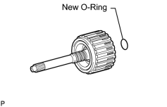
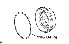
(a) Coat a new O-ring with ATF, and install it to the input shaft.
|
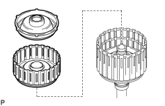
(b) Install the forward clutch piston and coast clutch piston to the input shaft. |
|
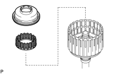
(c) Coat a new O-ring with ATF, and install it to the No. 1 clutch balancer. |
|
(d) Install the forward clutch return spring and No. 1 clutch balancer to the input shaft. NOTICE:
Be careful not to damage the O-rings. |
|
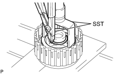
(e) Place SST on the No. 1 clutch balancer, and compress the return spring with a press. SST: 09350-30020 09350-07040 NOTICE:
Stop pressing when the spring sheet is lowered to a position 1 to 2 mm (0.0394 to 0.0787 in.) from the snap ring groove to prevent the spring sheet from being deformed. |
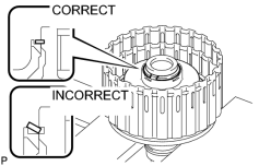
(f) Using SST, install the snap ring.
SST: 09350-30020
09350-07070
NOTICE:
Do not expand the snap ring excessively.
|
(g) Set the end gap of the snap ring in the balancer as shown in the illustration. NOTICE:
Be sure the end gap of the snap ring is not aligned with the spring retainer claw. |
40. INSTALL COAST CLUTCH DISC SET
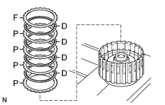
(a) Install the 4 plates, 4 discs and flange.
Install in order:
P - D - P - D - P - D - P - D - F
HINT:
P = Plate
D = Disc
F = Flange
NOTICE:
Before assembling new discs, soak them in ATF for at least 2 hours.
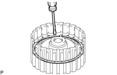
|
(b) Temporarily install the snap ring. |
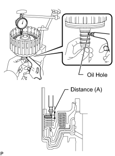
|
(c) Using a dial indicator, measure the moving distance (A) of the clutch flange at both ends across the diameter while blowing compressed air (196 kPa, 2.0 kgf/cm2, 28 psi) into the oil hole as shown in the illustration. Then choose from the 11 flange thicknesses in the table so that the measured value is within the standard value. Standard moving distance (A): 0.41 to 0.71 mm (0.0161 to 0.0280 in.) Flange Thickness:
|
(d) Temporarily remove the snap ring, install the selected flange and reinstall the snap ring.
41. INSTALL NO. 4 1-WAY CLUTCH ASSEMBLY
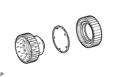
(a) Install the No. 2 clutch hub thrust washer to the coast clutch hub.
HINT:
Use a small amount of MP grease to make the thrust washer stay securely in place.
(b) Install the 1-way clutch to the coast clutch hub.
42. INSPECT NO. 4 1-WAY CLUTCH ASSEMBLY
43. INSTALL COAST CLUTCH HUB SUB-ASSEMBLY WITH NO. 4 1-WAY CLUTCH ASSEMBLY
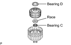
(a) Install the 2 thrust needle roller bearings, thrust bearing race and coast clutch hub with the No. 4 1-way clutch to the input shaft.
HINT:
Use a small amount of MP grease to make the thrust needle roller bearings and race stay securely in place.
Bearing and Race Diameter:
|
Item |
Inside |
Outside |
|---|---|---|
|
Bearing C |
21.05 to 21.3 mm (0.829 to 0.839 in.) |
39.63 to 39.88 mm (1.56 to 1.57 in.) |
|
Race |
22.8 to 23.1 mm (0.898 to 0.909 in.) |
44.5 to 44.75 mm (1.75 to 1.76 in.) |
|
Bearing D |
39.45 to 39.7 mm (1.55 to 1.56 in.) |
60.5 to 60.75 mm (2.38 to 2.39 in.) |
44. INSTALL FORWARD MULTIPLE DISC CLUTCH DISC SET
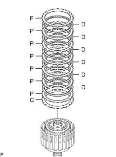
(a) Install the cushion plate, 6 plates, 6 discs and flange to the input shaft.
Install in order:
C - P - D - P - D - P - D - P - D - P - D - P - D - F
HINT:
C = Cushion plate
P = Plate
D = Disc
F = Flange
NOTICE:
Before assembling new discs, soak them in ATF for at least 2 hours.
|
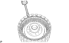
(b) Temporarily install the snap ring. |
|
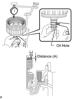
(c) Using a dial indicator, measure the moving distance (A) of the clutch flange at both ends across the diameter while blowing compressed air (196 kPa, 2.0 kgf/cm2, 28 psi) into the oil hole as shown in the illustration. Then choose from the 12 flange thicknesses in the table so that the measured value is within the standard value. Standard moving distance (A): 0.85 to 1.15 mm (0.0335 to 0.0453 in.) Flange Thickness:
|
(d) Temporarily remove the snap ring, install the selected flange and reinstall the snap ring.
45. INSTALL INPUT SHAFT OIL SEAL RING
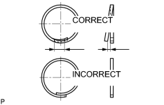
(a) Overlap the seal ring edges in the axial direction.
NOTICE:
- Overlapping the seal ring edges in the axial direction prevents damage to the seal ring.
- Do not overlap the seal ring edges in the radial direction, as this may damage the seal ring.
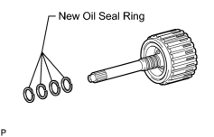
|
(b) Coat 4 new oil seal rings with ATF. |
(c) Squeeze the ends of the 4 oil seal rings together, and then install them to the input shaft groove.
NOTICE:
Do not excessively widen the rings.
HINT:
After installing the oil seal rings, check that they rotate smoothly.
46. INSTALL INPUT SHAFT ASSEMBLY
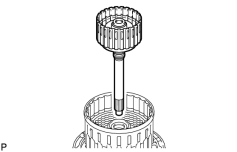
(a) Install the input shaft to the clutch drum.
47. INSTALL FORWARD CLUTCH HUB SUB-ASSEMBLY
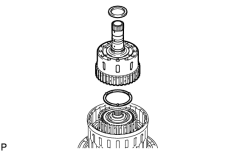
(a) Install the No. 3 clutch hub thrust washer, forward clutch hub and thrust needle roller bearing to the clutch drum.
NOTICE:
Before installing the forward clutch hub, apply ATF to the forward clutch hub bush sliding surfaces. After the installation, check that the forward clutch hub rotates smoothly.
HINT:
Use a small amount of MP grease to make the thrust needle roller bearing and thrust washer stay securely in place.
Bearing Diameter:
|
Item |
Inside |
Outside |
|---|---|---|
|
Bearing |
46.45 to 46.7 mm (1.83 to 1.84 in.) |
64.3 to 64.55 mm (2.53 to 2.54 in.) |
48. INSTALL REVERSE CLUTCH HUB SUB-ASSEMBLY
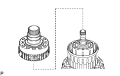
(a) Install the reverse clutch hub to the clutch drum.
NOTICE:
Before installing the reverse clutch hub, apply ATF to the reverse clutch hub bush sliding surfaces. After the installation, check that the reverse clutch rotates smoothly.
49. INSTALL REAR CLUTCH DISC SET
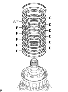
(a) Install the flange, 5 discs, 4 plates, selected flange, cushion plate and reverse clutch reaction sleeve to the clutch drum.
Install in order:
F - D - P - D - P - D - P - D - P - D - S/F - C
HINT:
F = Flange
D = Disc
P = Plate
S/F = Selected flange
C = Cushion plate
(b) Using a screwdriver, install the snap ring to the clutch drum.
50. INSTALL NO. 2 1-WAY CLUTCH ASSEMBLY
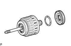
(a) Install the clutch drum thrust washer to the clutch drum.
HINT:
Use a small amount of MP grease to make the thrust washer stay securely in place.
(b) Install the 1-way clutch to the clutch drum.
51. INSPECT NO. 2 1-WAY CLUTCH ASSEMBLY
52. INSTALL CLUTCH DRUM AND INPUT SHAFT ASSEMBLY
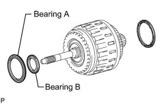
(a) Install the 2 thrust needle roller bearings.
HINT:
Use a small amount of MP grease to make the thrust needle roller bearings stay securely in place.
Bearing Diameter:
|
Item |
Inside |
Outside |
|---|---|---|
|
Bearing A |
71.96 to 72.26 mm (2.83 to 2.84 in.) |
85.25 to 85.6 mm (3.36 to 3.37 in.) |
|
Bearing B |
36.45 to 36.7 mm (1.44 to 1.45 in.) |
52.96 to 53.26 mm (2.09 to 2.10 in.) |
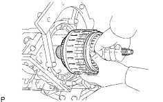
(b) Coat the clutch drum thrust washer with petroleum jelly and install it onto the clutch drum and input shaft assembly.
|
(c) Install the clutch drum and input shaft assembly to the transmission case. |
53. INSTALL OIL PUMP ASSEMBLY
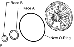
(a) Coat a new O-ring with ATF, and install it to the oil pump.
(b) Install the 2 thrust bearing races to the front oil pump.
Thrust Bearing Race Diameter:
|
Item |
Inside |
Outside |
|---|---|---|
|
Race A |
74.26 to 74.56 mm (2.92 to 2.94 in.) |
87.39 to 87.74 mm (3.44 to 3.45 in.) |
|
Race B |
38.0 to 38.3 mm (1.50 to 1.51 in.) |
53.9 to 54.1 mm (2.12 to 2.13 in.) |
|
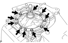
(c) Pass the input shaft through the center hole of the oil pump, and align the bolt holes of the oil pump assembly with the transmission case. |
(d) Hold the input shaft, and lightly press the oil pump body to slide the oil seal rings into the overdrive direct clutch drum.
(e) Apply seal packing to the flanges of the bolts.
Seal packing:
Toyota Genuine Seal Packing 1281, Three Bond 1281 or equivalent
NOTICE:
Do not allow seal packing to contact the bolt threads.
(f) Install the 10 bolts.
Torque: 21 N·m (214 kgf·cm, 15 ft·lbf)
NOTICE:
During installation, do not allow oil to contact the bolts or the surface of the oil pump body.
54. INSPECT INDIVIDUAL PISTON OPERATION
55. INSTALL MANUAL VALVE LEVER SHAFT OIL SEAL
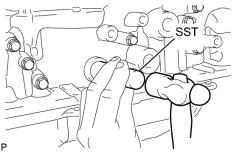
(a) Using SST, tap in 2 new oil seals.
SST: 09350-30020
09350-07110
(b) Coat the lips of the oil seals with MP grease.
56. INSTALL MANUAL VALVE LEVER SUB-ASSEMBLY
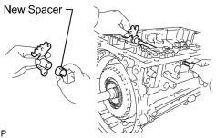
(a) Install a new spacer to the manual valve lever.
(b) Push the manual valve lever shaft through the transmission case, and install the manual valve lever to the shaft.
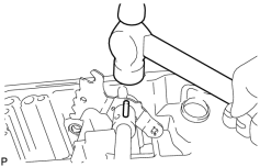
|
(c) Using a hammer, tap in a new spring pin. |
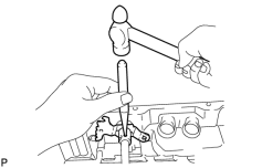
|
(d) Align the manual valve lever indentation with the spacer hole, and stake them together with the punch. |
(e) Check that the shaft rotates smoothly.
57. INSTALL PARKING LOCK PAWL
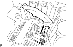
(a) Install a new E-ring to the shaft.
(b) Install the parking lock pawl, shaft and spring.
58. INSTALL PARKING LOCK ROD SUB-ASSEMBLY
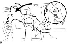
(a) Connect the parking lock rod to the manual valve lever.
59. INSTALL PARKING LOCK PAWL BRACKET
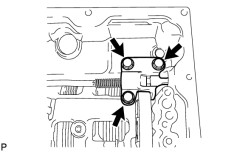
(a) Place the parking lock pawl bracket onto the transmission case and install the 3 bolts.
Torque: 18 N·m (184 kgf·cm, 13 ft·lbf)
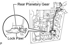
|
(b) Move the manual valve lever to the P position, and confirm that the planetary ring gear is correctly locked by the lock pawl. |
60. INSTALL B-1 ACCUMULATOR VALVE
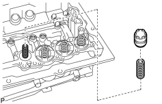
(a) Install the 2 springs and accumulator valve to the hole.
Spring Diameter:
|
Spring |
Free Length Outer Diameter |
Color |
|---|---|---|
|
B-1 Inner |
44.98 mm (1.77 in.) 11.30 mm (0.445 in.) |
Natural |
|
B-1 Outer |
46.36 mm (1.83 in.) 17.10 mm (0.673 in.) |
Natural |
61. INSTALL C-3 ACCUMULATOR PISTON
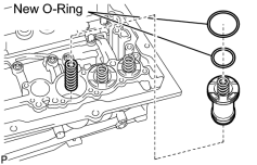
(a) Coat 2 new O-rings with ATF, and install them to the piston.
(b) Install the spring and accumulator piston to the hole.
Spring Diameter:
|
Spring |
Free Length Outer Diameter |
Color |
|---|---|---|
|
C-3 |
76.65 mm (3.02 in.) 20.1 mm (0.791 in.) |
Natural |
62. INSTALL B-3 ACCUMULATOR PISTON
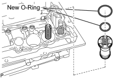
(a) Coat 2 new O-rings with ATF, and install them to the piston.
(b) Install the spring and accumulator piston to the hole.
Spring Diameter:
|
Spring |
Free Length Outer Diameter |
Color |
|---|---|---|
|
B-3 |
64.50 mm (2.54 in.) 19.5 mm (0.768 in.) |
Orange |
63. INSTALL C-2 ACCUMULATOR PISTON
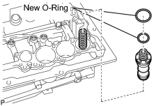
(a) Coat 2 new O-rings with ATF, and install them to the piston.
(b) Install the spring and accumulator piston to the hole.
Spring Diameter:
|
Spring |
Free Length Outer Diameter |
Color |
|---|---|---|
|
C-2 |
68.0 mm (2.68 in.) 16.1 mm (0.634 in.) |
Light green |
64. INSTALL CHECK BALL BODY
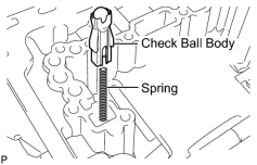
(a) Install the spring and check ball body.
65. INSTALL BRAKE DRUM GASKET
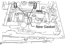
(a) Install 3 new brake drum gaskets.
66. INSTALL TRANSMISSION CASE GASKET
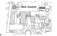
(a) Install 3 new transmission case gaskets.
67. INSTALL TRANSMISSION VALVE BODY ASSEMBLY
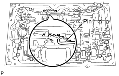
(a) Align the hole of the manual valve with the pin of the lever.
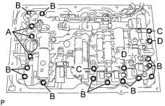
|
(b) Install the 19 bolts. Torque: 11 N·m (112 kgf·cm, 8 ft·lbf) HINT:
Each bolt length is indicated below. HINT: 36 mm (1.42 in.) for bolt A HINT: 25 mm (0.984 in.) for bolt B HINT: 45 mm (1.77 in.) for bolt C HINT: 50 mm (1.97 in.) for bolt D |
(c) Install the detent spring and detent spring cover with the bolt.
Torque: 10 N·m (102 kgf·cm, 7 ft·lbf)
68. INSTALL TRANSMISSION WIRE
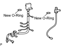
(a) Install 2 new O-rings to the transmission wires.
|
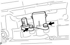
(b) Install the transmission wire harnesses. |
(c) Install the bolts.
Torque: 5.4 N·m (55 kgf·cm, 48 in·lbf)
|
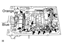
(d) Connect the 9 connectors to the solenoid valves. |
(e) Connect the 2 ATF temperature sensors with the 2 clamps and 2 bolts.
Torque: 10 N·m (102 kgf·cm, 7 ft·lbf)
Torque: 11 N·m (112 kgf·cm, 8 ft·lbf)
HINT:
Each bolt length is indicated below.
12 mm (0.472 in.) for bolt A
36 mm (1.42 in.) for bolt B
69. INSTALL VALVE BODY OIL STRAINER ASSEMBLY
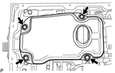
(a) Coat a new O-ring with ATF, and install it to the oil strainer.
(b) Install the oil strainer with the 4 bolts.
Torque: 10 N·m (102 kgf·cm, 7 ft·lbf)
70. INSTALL AUTOMATIC TRANSMISSION OIL PAN SUB-ASSEMBLY
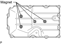
(a) Install the 4 magnets.
(b) Install a new gasket to the oil pan.
(c) Install the oil pan with the 12 bolts.
Torque: 7.4 N·m (75 kgf·cm, 65 in·lbf)
NOTICE:
- Make sure that there is no oil or foreign matter on the gasket seal surface and oil pan contact surface.
- Install the gasket so that there is no slack in the gasket, and make sure the entire circumference of the seal surface is level.
- Make sure that the 9 gasket drop prevention protrusions are set on the oil pan.
- When tightening the bolts of the oil pan, make sure that the gasket is not pinched between the gasket tightening area sleeve and the transmission seal surface.
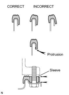
(d) Install the drain plug.
Torque: 20 N·m (204 kgf·cm, 15 ft·lbf)
71. INSTALL TRANSFER CASE ADAPTER RADIAL BALL BEARING
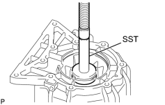
(a) Using SST and a press, press in the bearing until it stops.
SST: 09950-60010
09951-00650
SST: 09950-70010
09951-07150
(b) Using a screwdriver, install the snap ring.
72. INSTALL TRANSMISSION CASE ADAPTOR OIL SEAL
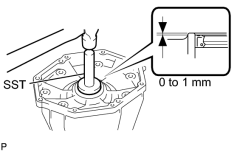
(a) Coat the lip of a new oil seal with ATF.
(b) Using SST and a hammer, tap in the oil seal.
Standard depth:
0 to 1 mm (0 to 0.0394 in.)
SST: 09950-60010
09951-00650
SST: 09950-70010
09951-07150
73. INSTALL REAR ADAPTOR TRANSFER
(a) Clean the threads of the bolts and case with non-residue solvent.
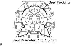
(b) Apply seal packing to the rear adaptor transfer.
Seal packing:
Toyota Genuine Seal Packing 1281,
Three Bond 1281 or equivalent
Seal diameter:
1.0 to 1.5 mm (0.0394 to 0.0591 in.)
|
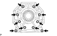
(c) Install the rear adaptor transfer with the 10 bolts. Torque: 34 N·m (345 kgf·cm, 25 ft·lbf) |
74. INSTALL AUTOMATIC TRANSMISSION HOUSING
(a) Clean the threads of the bolts and case with non-residue solvent.
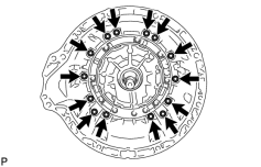
(b) Install the transmission housing with the 14 bolts.
Torque: 34 N·m (345 kgf·cm, 25 ft·lbf)
75. INSTALL AUTOMATIC TRANSMISSION BREATHER TUBE
(a) Coat a new O-ring with ATF and install it to the breather tube.
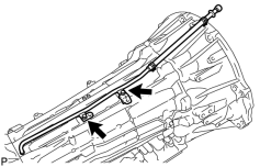
(b) Install the breather tube with the 2 bolts.
Torque: 5.4 N·m (55 kgf·cm, 48 in·lbf)
76. INSTALL TRANSMISSION OIL COOLER ASSEMBLY
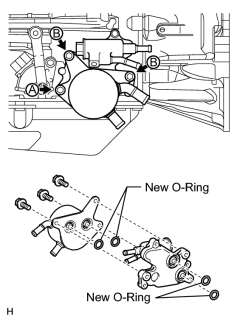
(a) Coat 4 new O-rings with ATF.
(b) Install the 4 O-rings, transmission oil thermostat and transmission oil cooler to the automatic transmission.
(c) Temporarily install bolt A. Install the bolts labeled B and tighten them to the specified torque. Then tighten bolt A to the specified torque.
Torque: 21 N·m (214 kgf·cm, 15 ft·lbf)
77. INSTALL SPEED SENSOR
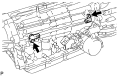
(a) Coat 2 new O-rings with ATF, and install them to the speed sensors.
(b) Install the 2 speed sensors.
(c) Install the 2 bolts.
Torque: 5.4 N·m (55 kgf·cm, 48 in·lbf)
78. INSTALL PARK/NEUTRAL POSITION SWITCH ASSEMBLY
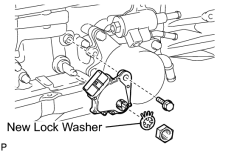
(a) Install the park/neutral position switch to the manual valve lever shaft, and temporarily install the adjusting bolt.
(b) Install a new lock washer and the nut.
Torque: 6.9 N·m (70 kgf·cm, 61 in·lbf)
(c) Temporarily install the control shaft lever RH.
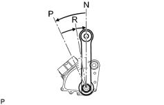
|
(d) Turn the control shaft lever RH counterclockwise until it stops, and then turn it clockwise 2 notches to set it to the N position. |
(e) Remove the control shaft lever RH.
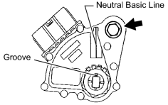
|
(f) Align the groove with the neutral basic line. |
(g) Hold the switch in position and tighten the bolt.
Torque: 13 N·m (133 kgf·cm, 10 ft·lbf)
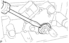
|
(h) Using a screwdriver, bend the tabs of the lock washer. |
79. INSTALL TRANSMISSION CONTROL SHAFT LEVER RH
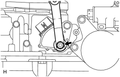
(a) Install the control shaft lever RH with the washer and nut.
Torque: 16 N·m (163 kgf·cm, 12 ft·lbf)

|

|