- Pressure sensor
- Open or short in pressure sensor circuit
- ECM
| Last Modified: 11-27-2007 | 1.6 C | |
| Service Category: Engine/Hybrid System | Section: Engine Control | |
| Model Year: 2008 | Model: LX570 | Doc ID: RM0000013HB00FX |
| Title: 3UR-FE ENGINE CONTROL: SFI SYSTEM: DESCRIPTION (2008 LX570) | ||
|
DTC |
P2431 |
Secondary Air Injection System Air Flow / Pressure Sensor Circuit Range / Performance Bank1 |
|
DTC |
P2432 |
Secondary Air Injection System Air Flow / Pressure Sensor Circuit Low Bank1 |
|
DTC |
P2433 |
Secondary Air Injection System Air Flow / Pressure Sensor Circuit High Bank1 |
|
DTC |
P2436 |
Secondary Air Injection System Air Flow / Pressure Sensor Circuit Range / Performance Bank 2 |
|
DTC |
P2437 |
Secondary Air Injection System Air Flow / Pressure Sensor Circuit Low Bank 2 |
|
DTC |
P2438 |
Secondary Air Injection System Air Flow / Pressure Sensor Circuit High Bank 2 |
DESCRIPTION
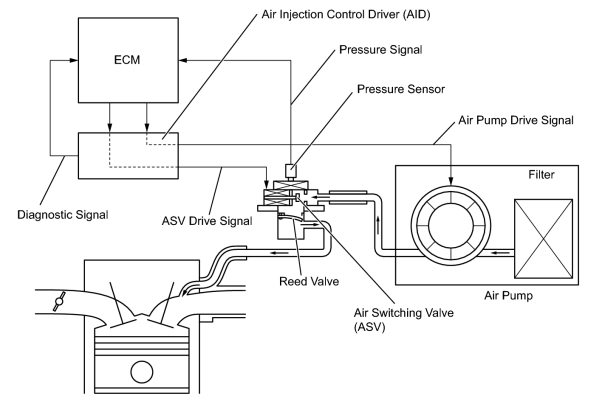
The Secondary Air injection (AIR) system consists of an air pump, the Air Switching Valve (ASV), a pressure sensor, the Air Injection Control Driver (AID) and the ECM. For a short time after a cold engine start, the AIR system pumps secondary air to the exhaust port of the cylinder head to purify the exhaust emissions. The secondary air is supplied by the air pump and is pumped to the exhaust port through the ASV.
The AID drives the ASV and the air pump according to command signals transmitted by the ECM. The pressure sensor detects the pressure in the secondary air passage when the AIR system is ON and OFF, and transmits a pressure signal to the ECM.
The AID is not only equipped to drive the pump and valve, but also with a diagnosis function to detect malfunctions in the AIR system circuit.
HINT:
As a large current is required to drive the air pump and ASV, an AID is installed to this system.
|
DTC Code |
DTC Detection Condition |
Trouble Area |
|---|---|---|
|
P2431 P2436 |
The pressure sensor indicates below 45.6 kPa (342 mmHg), or higher than 135 kPa (1013 mmHg) (2 trip detection logic). |
|
|
P2432 P2437 |
While the engine is running, the voltage output of the pressure sensor remains below 0.5 V (1 trip detection logic). |
|
|
P2433 P2438 |
While the engine is running, the voltage output of the pressure sensor remains higher than 4.5 V (1 trip detection logic). |
|
MONITOR DESCRIPTION
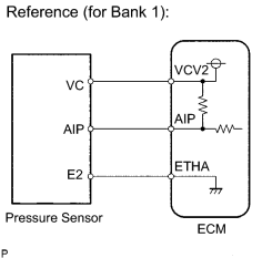
The ECM monitors the pressure in the secondary air passage using the pressure sensor located on the air switching valve in the secondary air injection system.
If there is a defect in the sensor or the sensor circuit, the voltage level deviates from the normal operating range, the ECM interprets this deviation as a malfunction in the pressure sensor or circuit and stores DTC(s).
MONITOR STRATEGY
|
Related DTCs |
P2431: Air flow/Pressure sensor circuit rationality P2432: Air flow/Pressure sensor circuit range check (Low voltage) P2433: Air flow/Pressure sensor circuit range check (High voltage) P2436: Air flow/Pressure sensor circuit rationality P2437: Air flow/Pressure sensor circuit range check (Low voltage) P2438: Air flow/Pressure sensor circuit range check (High voltage) |
|
Required Sensors/Components (Main) |
Pressure sensor |
|
Required Sensors/Components (Related) |
- |
|
Frequency of Operation |
Continuous |
|
Duration |
P2432, P2433, P2437, P2438: 0.5 seconds P2431, P2436: 5 seconds |
|
MIL Operation |
P2432, P2433, P2437, P2438: Immediate P2431, P2436: 2 driving cycles |
|
Sequence of Operation |
None |
TYPICAL ENABLING CONDITIONS
P2432, P2433, P2437 and P2438
|
Monitor runs whenever following DTCs not stored |
None |
|
All of following conditions met: |
- |
|
Starter |
OFF |
|
Battery voltage |
8 V or higher |
|
Engine switch |
On (IG) |
P2431 and P2436:
|
Monitor runs whenever following DTCs not stored |
P2432, P2433, P2437, P2438 (AIR Pressure Sensor - Low/High) |
|
Starter |
OFF |
|
Battery voltage |
8 V or higher |
|
Engine switch |
On (IG) |
TYPICAL MALFUNCTION THRESHOLDS
P2432 and P2437:
|
Air pressure sensor voltage |
Below 0.5 V |
P2433 and P2438:
|
Air pressure sensor voltage |
Higher than 4.5 V |
P2431 and P2436:
|
Air pressure |
Below 45.6 kPa (342 mmHg), or higher than 135 kPa (1013 mmHg) |
COMPONENT OPERATING RANGE
|
Air pressure sensor voltage |
Between 0.1 V and 4.8 V |
WIRING DIAGRAM
Refer to DTC P0412
 .
.
INSPECTION PROCEDURE
HINT:
Read freeze frame data using the Techstream. Freeze frame data records the engine condition when malfunctions are detected. When troubleshooting, freeze frame data can help determine if the vehicle was moving or stationary, if the engine was warmed up or not, if the air-fuel ratio was lean or rich, and other data from the time the malfunction occurred.
PROCEDURE
|
1. |
CHECK HARNESS AND CONNECTOR (PRESSURE SENSOR - ECM) |
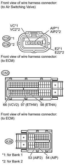
(a) Disconnect the C35 or C36 pressure sensor connector.
(b) Disconnect the A38 and C53 ECM connectors.
(c) Measure the resistance according to the value(s) in the table below.
Standard Resistance:
|
Tester Connection |
Condition |
Specified Condition |
|---|---|---|
|
C35-3 (AIP) - A38-54 (AIP) |
Always |
Below 1 Ω |
|
C35-2 (VC) - C53-66 (VCV2) |
Always |
Below 1 Ω |
|
C35-4 (E2) - C53-98 (ETHA) |
Always |
Below 1 Ω |
|
C36-3 (AIP2) - A38-53 (AIP2) |
Always |
Below 1 Ω |
|
C36-2 (VC2) - C53-66 (VCV2) |
Always |
Below 1 Ω |
|
C36-4 (E22) - C53-97 (ETHW) |
Always |
Below 1 Ω |
|
C35-3 (AIP) or A38-54 (AIP) - Body ground |
Always |
10 kΩ or higher |
|
C35-2 (VC) or C53-66 (VCV2) - Body ground |
Always |
10 kΩ or higher |
|
C36-3 (AIP2) or A38-53 (AIP2) - Body ground |
Always |
10 kΩ or higher |
|
C36-2 (VC2) or C53-66 (VCV2) - Body ground |
Always |
10 kΩ or higher |
|

|
2. |
INSPECT AIR SWITCHING VALVE (PRESSURE SENSOR) |
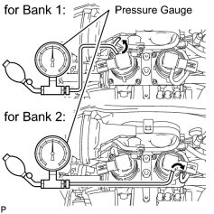
(a) Connect a pressure gauge to the air pressure sensor as shown in the illustration.
(b) Connect the Techstream to the DLC3.
(c) Turn the engine switch on (IG) and turn the Techstream on.
(d) Enter the following menus: Powertrain / Engine and ECT / Data List / Air pump pressure (absolute) and Air Pump2 Pressure (Absolute).
(e) Check that the pressure displayed on the Techstream fluctuates when applying the pressure to the pressure sensor with the pressure gauge.
NOTICE:
Do not let foreign matter enter the sensor when applying pressure.
OK:
Pressure fluctuates in response to pressure applied with pressure gauge.
HINT:
The Techstream displays the air pump pressure as absolute pressure.
|

|

|