| Last Modified: 11-27-2007 | 1.6 J | |
| Service Category: Audio/Visual/Telematics | Section: Navigation/Multi Info Display | |
| Model Year: 2008 | Model: LX570 | Doc ID: RM0000014ST024X |
| Title: NAVIGATION / MULTI INFO DISPLAY: NAVIGATION SYSTEM: DESCRIPTION (2008 LX570) | ||
|
Microphone Circuit between Overhead J/B and Multi-display |
DESCRIPTION
w/o LEXUS Link System:
This circuit sends a microphone signal from the microphone to the display and navigation module display. It also supplies power from the display and navigation module display to the microphone.
w/ LEXUS Link System:
This circuit sends a microphone signal from the microphone to the display and navigation module display through the telephone ECU assembly. It also supplies power from the telephone ECU assembly to the microphone.
WIRING DIAGRAM
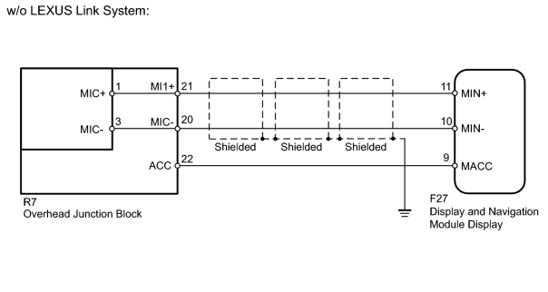
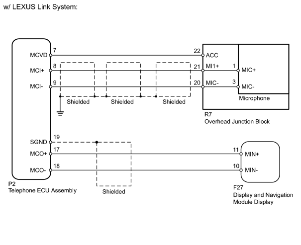
INSPECTION PROCEDURE
PROCEDURE
|
1. |
CHECK DISPLAY AND NAVIGATION MODULE DISPLAY |
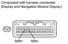
|
(a) Check the waveform of the microphone using an oscilloscope.
|
|

|
2. |
CHECK LEXUS LINK SYSTEM |
(a) Check if the vehicle is equipped with the LEXUS link system.
Result
|
Result |
Proceed to |
|---|---|
|
w/o LEXUS Link System |
A |
|
w/ LEXUS Link System |
B |
|
|
3. |
CHECK HARNESS AND CONNECTOR (OVERHEAD JUNCTION BLOCK - DISPLAY AND NAVIGATION MODULE DISPLAY) |
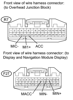
|
(a) Disconnect the R7 overhead junction block connector. |
(b) Disconnect the F27 display connector.
(c) Measure the resistance according to the value(s) in the table below.
Standard Resistance:
|
Tester Connection |
Condition |
Specified Condition |
|---|---|---|
|
F27-9 (MACC) - R7-22 (ACC) |
Always |
Below 1 Ω |
|
F27-11 (MIN+) - R7-21 (MI1+) |
Always |
Below 1 Ω |
|
F27-10 (MIN-) - R7-20 (MIC-) |
Always |
Below 1 Ω |
|
F27-9 (MACC) - Body ground |
Always |
10 kΩ or higher |
|
F27-11 (MIN+) - Body ground |
Always |
10 kΩ or higher |
|
F27-10 (MIN-) - Body ground |
Always |
10 kΩ or higher |
|
|
4. |
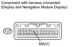
CHECK DISPLAY AND NAVIGATION MODULE DISPLAY (MACC VOLTAGE) |
|
(a) Reconnect the F27 display connector. |
(b) Measure the voltage according to the value(s) in the table below.
Standard Voltage:
|
Tester Connection |
Switch Condition |
Specified Condition |
|---|---|---|
|
F27-9 (MACC) - Body ground |
Engine switch on (ACC) |
4 to 6 V |
|
|
5. |
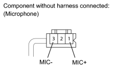
CHECK MICROPHONE ASSEMBLY |
|
(a) Remove the microphone from the overhead junction block
|

(b) Measure the resistance according to the value(s) in the table below.
Standard Resistance:
|
Tester Connection |
Condition |
Specified Condition |
|---|---|---|
|
1 (MIC+) - 3 (MIC-) |
Always |
1.9 to 2.2 kΩ |
|
|
6. |
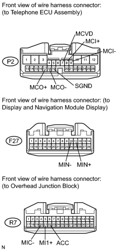
CHECK HARNESS AND CONNECTOR (TELEPHONE ECU - DISPLAY AND NAVIGATION MODULE DISPLAY AND OVERHEAD JUNCTION BLOCK) |
|
(a) Disconnect the P2 ECU connector. |
(b) Disconnect the F27 display connector.
(c) Disconnect the R7 junction block connector.
(d) Measure the resistance according to the value(s) in the table below.
Standard Resistance:
|
Tester Connection |
Condition |
Specified Condition |
|---|---|---|
|
P2-17 (MCO+) - F27-11 (MIN+) |
Always |
Below 1 Ω |
|
P2-18 (MCO-) - F27-10 (MIN-) |
Always |
Below 1 Ω |
|
P2-7 (MCVD) - R7-22 (ACC) |
Always |
Below 1 Ω |
|
P2-8 (MCI+) - R7-21 (MI1+) |
Always |
Below 1 Ω |
|
P2-9 (MCI-) - R7-20 (MIC-) |
Always |
Below 1 Ω |
|
P2-17 (MCO+) - Body ground |
Always |
10 kΩ or higher |
|
P2-18 (MCO-) - Body ground |
Always |
10 kΩ or higher |
|
P2-19 (SGND) - Body ground |
Always |
10 kΩ or higher |
|
P2-7 (MCVD) - Body ground |
Always |
10 kΩ or higher |
|
P2-8 (MCI+) - Body ground |
Always |
10 kΩ or higher |
|
P2-9 (MCI-) - Body ground |
Always |
10 kΩ or higher |
|
|
7. |
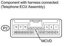
CHECK TELEPHONE ECU ASSEMBLY (TACC VOLTAGE) |
|
(a) Reconnect the P2 ECU connector. |
(b) Measure the voltage according to the value(s) in the table below.
Standard Voltage:
|
Tester Connection |
Switch Condition |
Specified Condition |
|---|---|---|
|
P2-7 (MCVD) - Body ground |
Engine switch on (ACC) |
4 to 6 V |
|
|
8. |
CHECK MICROPHONE ASSEMBLY |
|
|
(a) Remove the microphone from the overhead junction block
|
(b) Measure the resistance according to the value(s) in the table below.
Standard Resistance:
|
Tester Connection |
Condition |
Specified Condition |
|---|---|---|
|
1 (MIC+) - 3 (MIC-) |
Always |
1.9 to 2.2 kΩ |
|

|

|