| Last Modified: 11-27-2007 | 1.6 A | |
| Service Category: Drivetrain | Section: Axle/Differential | |
| Model Year: 2008 | Model: LX570 | Doc ID: RM0000016GD00RX |
| Title: AXLE AND DIFFERENTIAL: FRONT DIFFERENTIAL CARRIER ASSEMBLY: REASSEMBLY (2008 LX570) | ||
REASSEMBLY
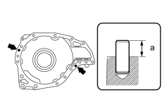
1. INSTALL FRONT DIFFERENTIAL CARRIER STRAIGHT PIN
|
(a) Using a plastic-faced hammer, tap in the straight pins until the protrusion height shown in the illustration is within the specification. Standard depth (a): 9.5 to 10.0 mm (0.374 to 0.394 in.) |
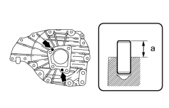
2. INSTALL FRONT DIFFERENTIAL TUBE STRAIGHT PIN
|
(a) Using a plastic-faced hammer, tap in the straight pins until the protrusion height shown in the illustration is within the specification. Standard depth (a): 9.5 to 10.0 mm (0.374 to 0.394 in.) |
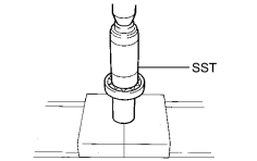
3. INSTALL FRONT DIFFERENTIAL SIDE GEAR SHAFT RH BEARING
|
(a) Using SST and a press, press in the bearing. SST: 09223-00010 |
|
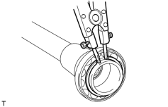
(b) Using a snap ring expander, install a new snap ring. |
4. INSTALL DIFFERENTIAL SIDE GEAR SHAFT SUB-ASSEMBLY RH
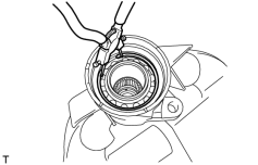
|
(a) Install the side gear shaft into the differential tube. |
(b) Using snap ring pliers, install a new snap ring.
5. INSTALL DIFFERENTIAL SIDE GEAR SHAFT OIL SEAL
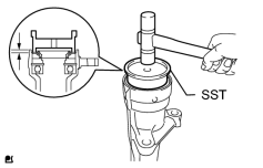
|
(a) Using SST and a plastic-faced hammer, tap in a new oil seal. SST: 09608-32010 Standard oil seal depth: 4.8 to 5.8 mm (0.189 to 0.228 in.) |
(b) Coat the lip of the oil seal with MP grease.
6. INSTALL FRONT NO. 1 DIFFERENTIAL CASE SUB-ASSEMBLY
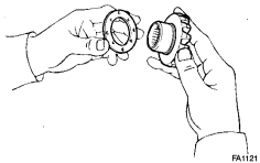
|
(a) Install the 2 side gear thrust washers onto the 2 side gears. HINT:
Using the table below, select 2 thrust washers which will ensure that the backlash is within the specifications. |
(b) Install the 2 side gears (with thrust washers), 2 pinion gears, 2 pinion gear thrust washers and pinion shaft into the differential case assembly.
HINT:
- Align the holes of the differential case assembly and pinion shaft.
- Apply hypoid gear oil to each sliding surface and rotating part.
(c) Measure the side gear backlash.
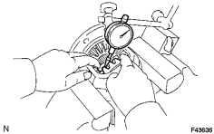
|
(1) Using a dial indicator, measure the side gear backlash while holding one pinion gear toward the differential case assembly. Standard backlash: 0 to 0.15 mm (0 to 0.00591 in.) If the backlash is not within the specification, replace the 2 side gear thrust washers. Use the table below to select 2 thrust washers of the same thickness which will ensure that the backlash is within the specification. Standard Thrust Washer Thickness:
|
|
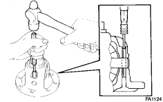
(d) Using a pin punch and hammer, tap in the straight pin through the differential case and hole of the pinion shaft. |
(e) Stake the differential case.
7. INSTALL DIFFERENTIAL RING GEAR
|
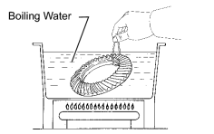
(a) Clean the contact surfaces of the differential case and ring gear. |
(b) Heat the ring gear to about 100°C (212°F) in boiling water.
(c) Carefully take the ring gear out of the boiling water.
(d) After the moisture on the ring gear has completely evaporated, quickly align the matchmarks on the ring gear and differential case and set the ring gear onto the differential case. Then temporarily install the 10 bolts so that the bolt holes in the ring gear and differential case are aligned.
(e) After the ring gear cools down sufficiently, remove the 10 bolts. Then apply adhesive to the 10 bolts and install them.
Torque: 137 N·m (1397 kgf·cm, 101 ft·lbf)
Adhesive:
Toyota Genuine Adhesive 1360K, Three Bond 1360K or equivalent
8. INSTALL FRONT DIFFERENTIAL CASE BEARING
|
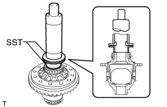
(a) Using SST and a press, press in the 2 bearings (inner race). SST: 09316-20011 SST: 09316-60011 09316-00041 |
9. INSTALL FRONT DIFFERENTIAL CASE BEARING
HINT:
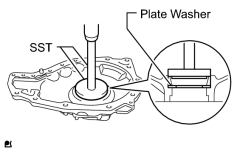
When replacing the 2 differential case bearings, fit the thinnest washer to each bearing. When reusing the bearings, fit a washer of the same thickness as the one removed to each bearing.
|
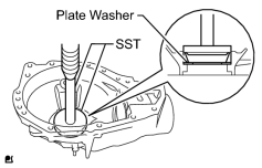
(a) Install a new plate washer to the shaft bearing retainer. |
(b) Using SST and a press, press the bearing (outer race) into the differential case bearing retainer.
SST: 09950-60020
09951-00890
SST: 09950-70010
09951-07150
|
(c) Install a new plate washer onto the differential carrier. |
(d) Using SST and a press, press the bearing (outer race) into the differential carrier assembly.
SST: 09950-60020
09951-00890
SST: 09950-70010
09951-07150
10. INSTALL FRONT DRIVE PINION FRONT RADIAL BALL BEARING
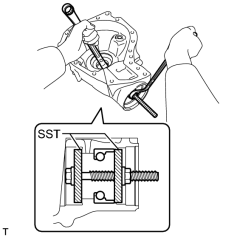
|
(a) Using SST, install the bearing (outer race). SST: 09950-00020 09951-00810 09951-00890 |
11. INSTALL FRONT DRIVE PINION REAR TAPERED ROLLER BEARING
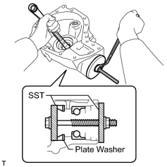
|
(a) Using SST, install the washer and bearing (outer race). SST: 09950-00020 09951-00890 09951-01030 HINT:
After installing the washer, check the tooth contact pattern. If necessary, replace the washer with one of a different thickness. |
12. INSTALL FRONT DRIVE PINION REAR TAPERED ROLLER BEARING
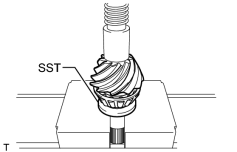
|
(a) Using SST and a press, press in the bearing (inner race). SST: 09506-35010 |
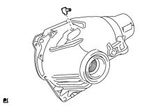
13. INSTALL FRONT DIFFERENTIAL UNION
|
(a) Install the front differential union to the differential carrier. |
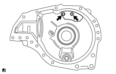
14. INSTALL FRONT DIFFERENTIAL BREATHER PLUG OIL DEFLECTOR
|
(a) Install the 2 bolts and oil deflector. Torque: 7.0 N·m (71 kgf·cm, 62 in·lbf) |
15. TEMPORARILY INSTALL DIFFERENTIAL DRIVE PINION
16. INSTALL FRONT NO. 1 DIFFERENTIAL CASE SUB-ASSEMBLY
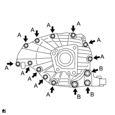
17. INSTALL FRONT DIFFERENTIAL CROSS SHAFT BEARING RETAINER
|
(a) Install the differential cross shaft bearing retainer and differential support with the 14 bolts. Torque: 65 N·m (633 kgf·cm, 48 ft·lbf) Torque: 155 N·m (1581 kgf·cm, 114 ft·lbf) |
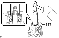
18. INSTALL FRONT DRIVE PINION FRONT RADIAL BALL BEARING
|
(a) Using SST and a hammer, lightly tap in the bearing (inner race) to install it. SST: 09316-60011 09316-00041 |
19. INSTALL FRONT DIFFERENTIAL DRIVE PINION OIL SLINGER
20. INSPECT DIFFERENTIAL DRIVE PINION PRELOAD
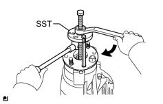
|
(a) Using SST, install the companion flange. SST: 09950-30012 09951-03010 09953-03010 09954-03010 09955-03030 09956-03020 |
(b) Coat the threads of the nut with hypoid gear oil.
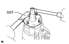
|
(c) Using SST, hold the companion flange. SST: 09330-00021 09330-00030 |
(d) Tighten the nut until the standard preload is reached.
Torque: 451 N·m (4599 kgf·cm, 332 ft·lbf)
NOTICE:
As there is no spacer, tighten the nut a little at a time, being careful not to overtighten it.
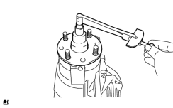
|
(e) Using a torque wrench, measure the preload of the backlash between the drive pinion and ring gear. Standard Preload (at Starting):
If necessary, disassemble and inspect the differential assembly. |
21. ADJUST BACKLASH BETWEEN DIFFERENTIAL RING GEAR AND DIFFERENTIAL DRIVE PINION
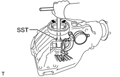
|
(a) Using SST and a dial indicator, measure the ring gear backlash. SST: 09564-33010 Standard backlash: 0.17 to 0.27 mm (0.00670 to 0.0106 in.) If the backlash is not within the specification, adjust it by either increasing or decreasing the thickness of the washers on both sides by an equal amount. HINT:
Standard Plate Washer Thickness:
|
22. INSPECT TOTAL PRELOAD
|
|
(a) Using a torque wrench, measure the preload with the teeth of the drive pinion and ring gear in contact. Standard Total Preload (at starting):
If necessary, disassemble and inspect the differential. |
23. INSPECT TOOTH CONTACT BETWEEN RING GEAR AND DRIVE PINION
(a) Remove the bearing retainer and differential case.
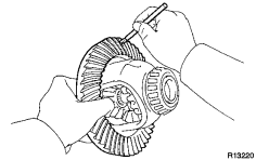
|
(b) Coat 3 or 4 teeth at 3 different positions on the ring gear with Prussian blue. |
(c) Install the differential case to the differential carrier.
|
|
(d) Install the differential cross shaft bearing retainer and front differential front support assembly LH with the 14 bolts. Torque: 65 N·m (633 kgf·cm, 48 ft·lbf) Torque: 155 N·m (1581 kgf·cm, 114 ft·lbf) |
(e) Hold the companion flange firmly and rotate it in both directions.
(f) Remove the 14 bolts, differential case, shaft bearing retainer and front support.
(g) Inspect the tooth contact pattern.
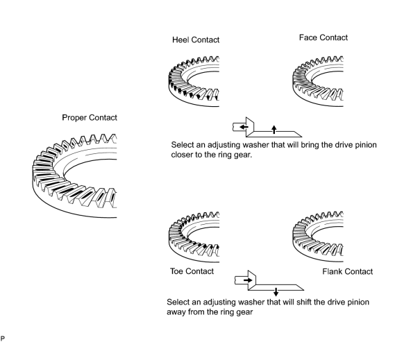
If the teeth are not engaged properly, use the following chart to select the appropriate drive pinion washer for correction.
Standard Drive Pinion Washer Thickness:
|
Specified Condition |
Specified Condition |
|---|---|
|
1.815 to 1.835 mm (0.0715 to 0.0722 in.) |
2.065 to 2.085 mm (0.0813 to 0.0821 in.) |
|
1.840 to 1.860 mm (0.0724 to 0.0732 in.) |
2.090 to 2.110 mm (0.0823 to 0.0831 in.) |
|
1.865 to 1.885 mm (0.0734 to 0.0742 in.) |
2.115 to 2.135 mm (0.0793 to 0.0841 in.) |
|
1.890 to 1.910 mm (0.0744 to 0.0752 in.) |
2.140 to 2.160 mm (0.0843 to 0.0850 in.) |
|
1.915 to 1.935 mm (0.0754 to 0.0762 in.) |
2.165 to 2.185 mm (0.0852 to 0.0860 in.) |
|
1.940 to 1.960 mm (0.0764 to 0.0772 in.) |
2.190 to 2.210 mm (0.0862 to 0.0870 in.) |
|
1.965 to 1.985 mm (0.0774 to 0.0781 in.) |
2.215 to 2.235 mm (0.0872 to 0.0880 in.) |
|
1.990 to 2.010 mm (0.0783 to 0.0791 in.) |
2.240 to 2.260 mm (0.0882 to 0.0890 in.) |
|
2.015 to 2.035 mm (0.0793 to 0.0801 in.) |
2.265 to 2.285 mm (0.0892 to 0.0900 in.) |
|
2.040 to 2.060 mm (0.0803 to 0.0811 in.) |
- |
24. REMOVE FRONT DRIVE PINION COMPANION FLANGE SUB-ASSEMBLY

25. REMOVE FRONT DIFFERENTIAL DRIVE PINION OIL SLINGER
26. REMOVE FRONT DIFFERENTIAL CROSS SHAFT BEARING RETAINER
27. REMOVE FRONT NO. 1 DIFFERENTIAL CASE SUB-ASSEMBLY
28. REMOVE DIFFERENTIAL DRIVE PINION
29. REMOVE FRONT DRIVE PINION FRONT RADIAL BALL BEARING
30. INSTALL FRONT DIFFERENTIAL DRIVE PINION BEARING SPACER
(a) Install a new bearing spacer.
31. TEMPORARILY INSTALL DIFFERENTIAL DRIVE PINION
32. INSTALL FRONT NO. 1 DIFFERENTIAL CASE SUB-ASSEMBLY
33. INSTALL FRONT DIFFERENTIAL CROSS SHAFT BEARING RETAINER
(a) Remove any old FIPG material and be careful not to drop oil on the contact surfaces of the differential carrier and shaft bearing retainer.
(b) Wipe off any residual FIPG material on the contact surface using gasoline or alcohol.
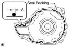
|
(c) Apply seal packing to the shaft bearing retainer as shown in the illustration. Seal packing: Toyota Genuine Seal Packing 1281, Three Bond 1281 or equivalent Standard Seal Diameter (A): 2.0 to 3.0 mm (0.0788 to 0.118 in.) HINT:
Install the shaft bearing retainer within 10 minutes of applying seal packing. |
|
|
(d) Install the front differential cross shaft bearing retainer and front differential front support assembly LH with the 11 bolts (A), and 3 new bolts (B). Torque: 65 N·m (633 kgf·cm, 48 ft·lbf) Torque: 155 N·m (1581 kgf·cm, 114 ft·lbf) |
34. INSTALL FRONT DRIVE PINION FRONT RADIAL BALL BEARING
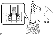
|
(a) Using SST and a hammer, lightly tap in the bearing (inner race) to install it. SST: 09316-60011 09316-00041 |
35. INSTALL FRONT DIFFERENTIAL DRIVE PINION OIL SLINGER
36. INSTALL FRONT DIFFERENTIAL CARRIER OIL SEAL
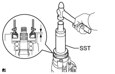
|
(a) Using SST and a hammer, tap in a new oil seal. SST: 09502-12010 SST: 09316-60011 09316-00041 Standard oil seal depth: 5.6 to 6.6 mm (0.221 to 0.260 in.) |
(b) Coat the lip of the oil seal with MP grease.
37. INSTALL FRONT DRIVE PINION COMPANION FLANGE SUB-ASSEMBLY
|
|
(a) Using SST, install the companion flange. SST: 09950-30012 09951-03010 09953-03010 09954-03010 09955-03030 09956-03020 |
38. INSPECT DIFFERENTIAL DRIVE PINION PRELOAD
|
|
(a) Using SST, hold the companion flange. SST: 09330-00021 09330-00030 |
(b) Coat the threads of a new nut with hypoid gear oil.
(c) Install the nut by tightening it until the standard preload is reached.
Torque: 451 N·m (4599 kgf·cm, 332 ft·lbf)
|
|
(d) Using a torque wrench, measure the preload of the backlash between the drive pinion and ring gear. Standard Preload (at Starting):
If the preload is more than the specification, replace the bearing spacer. If the preload is less than the specification, tighten the nut with 13 N*m (130 kgf*cm, 9 ft.*lbf) of torque at a time until the specified preload is reached. Torque: 451 N·m (4599 kgf·cm, 332 ft·lbf) If the maximum torque is exceeded while tightening the nut, replace the bearing spacer and repeat the preload procedure. HINT:
Do not loosen the nut to reduce the preload. |
39. INSPECT TOTAL PRELOAD
|
|
(a) With the drive pinion contacting the tooth side of the ring gear, use a torque wrench to measure the total preload. Standard Total Preload (at starting):
|
40. INSPECT BACKLASH BETWEEN DIFFERENTIAL RING GEAR AND DIFFERENTIAL DRIVE PINION
|
|
(a) Using SST and a dial indicator, measure the ring gear backlash. SST: 09564-33010 Standard backlash: 0.17 to 0.27 mm (0.00670 to 0.0106 in.) |
41. INSPECT RUNOUT OF FRONT DRIVE PINION COMPANION FLANGE SUB-ASSEMBLY
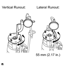
|
(a) Using a dial indicator, measure the runout of the companion flange vertically and laterally. Maximum Runout:
If the runout is more than the maximum, replace the companion flange. |
42. STAKE FRONT DRIVE PINION COMPANION FLANGE FRONT NUT
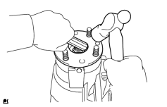
|
(a) Using a chisel and hammer, stake the nut. |
43. INSTALL DIFFERENTIAL SIDE GEAR SHAFT OIL SEAL
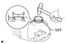
|
(a) Using SST and a plastic-faced hammer, tap in a new oil seal until its surface is flush with the differential carrier end. SST: 09608-32010 |
(b) Coat the lip of the oil seal with MP grease.
Standard oil seal depth:
-0.45 to 0.45 mm (-0.0177 to 0.0177 in.)
44. INSTALL DIFFERENTIAL EXTENSION FLANGE TUBE
(a) Remove any old FIPG material and be careful not to drop oil on the contact surfaces of the differential tube and bearing retainer.
(b) Wipe off any residual FIPG material on the contact surface using gasoline or alcohol.
|
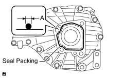
(c) Apply seal packing to the bearing retainer as shown in the illustration. Seal packing: Toyota Genuine Seal Packing 1281, Three Bond 1281 or equivalent Standard Seal Diameter (A): 2.0 to 3.0 mm (0.0788 to 0.118 in.) HINT:
Install the differential tube within 10 minutes of applying seal packing. |
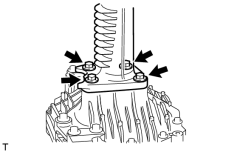
(d) Install the differential tube onto the bearing retainer.
|
(e) Install 4 new bolts. Torque: 65 N·m (663 kgf·cm, 48 ft·lbf) |

|

|