| Last Modified: 11-27-2007 | 1.6 A | |
| Service Category: Drivetrain | Section: Drive Shaft/Propeller Shaft | |
| Model Year: 2008 | Model: LX570 | Doc ID: RM0000016WX00KX |
| Title: DRIVE SHAFT / PROPELLER SHAFT: FRONT DRIVE SHAFT ASSEMBLY: REASSEMBLY (2008 LX570) | ||
REASSEMBLY
NOTICE:
Do not allow brake fluid, front differential oil, gasoline, or battery fluid to contact the drive shaft boots, as the boots may be damaged.
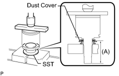
1. INSTALL FRONT DRIVE SHAFT DUST COVER LH
|
(a) Using SST, a steel plate and press, press in a new dust cover. SST: 09316-20011 Standard length (A): 108.4 to 109.0 mm (4.27 to 4.29 in.) NOTICE:
Be careful not to damage the dust cover. |
2. INSTALL FRONT AXLE OUTBOARD JOINT BOOT
|
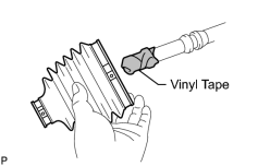
(a) Slide a new outboard joint boot onto the outboard joint shaft. HINT:
Before installing the boot, wrap vinyl tape around the spline of the shaft to prevent damaging the boot. |
|
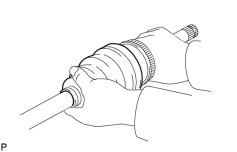
(b) Temporarily install the boot to the outboard joint shaft. |
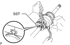
(c) Attach a new front No. 1 axle outboard joint boot setting clamp onto the boot.
|
(d) Using SST, pinch the clamp. SST: 09521-24010 NOTICE:
Do not overtighten SST. |
(e) Pack the outboard joint and boot with grease from a boot kit.
Standard grease capacity:
310 to 320 g (11.0 to 11.2 oz.)
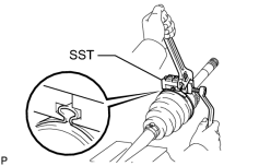
(f) Attach a new front No. 2 axle outboard joint boot setting clamp onto the boot.
|
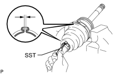
(g) Using SST, pinch the clamp. SST: 09521-24010 NOTICE:
Do not overtighten SST. |
|
(h) Using SST, adjust the clearance of the clamps. SST: 09240-00020 Standard clearance: 1.5 mm (0.0591 in.) |
3. TEMPORARILY INSTALL FRONT AXLE INBOARD JOINT BOOT
|
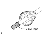
(a) Slide a new inboard joint boot onto the outboard joint shaft. HINT:
Before installing the boot, wrap vinyl tape around the spline of the shaft to prevent damaging the boot. |
4. INSTALL FRONT AXLE INBOARD JOINT SHAFT
|
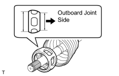
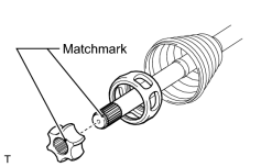
(a) Install the cage to the outboard joint shaft. NOTICE:
Insert the cage with its smaller inner diameter side facing the outboard joint. |
|
(b) Align the matchmarks placed before removal. |
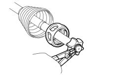
(c) Install the inner race.
|
(d) Using a snap ring expander, install a new snap ring. |
|
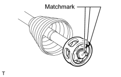
(e) Align the matchmarks placed before removal, and install the cage to the inner race. |
|
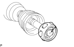
(f) Install the 6 balls. HINT:
Apply grease onto the balls to keep them from falling out. |
(g) Pack the inboard joint shaft and boot with grease from a boot kit.
Standard grease capacity:
314 to 324 g (11.1 to 11.4 oz.)
|
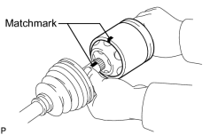
(h) Align the matchmarks placed before removal, and install the inboard joint shaft to the outboard joint shaft. |
(i) Install a new snap ring.
|
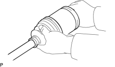
(j) Temporarily install the boot to the inboard joint shaft. HINT:
Make sure that the boot is on the shaft groove. |
|
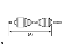
(k) Check that the 2 boots are not stretched or contracted when the drive shaft is at standard length. Standard drive shaft length (A): 583 mm (1.91 ft.) If the boots are stretched or contracted, correct them. |
|
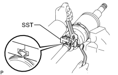
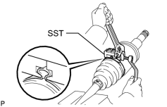
(l) Using SST, attach a new front No. 1 axle inboard joint boot setting clamp onto the boot. SST: 09521-24010 NOTICE:
Do not overtighten SST. |
|
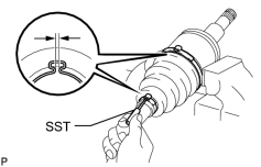
(m) Using SST, attach a new front No. 2 axle inboard joint boot setting clamp onto the boot. SST: 09521-24010 NOTICE:
Do not overtighten SST. |
|
(n) Using SST, adjust the clearance of the clamps. SST: 09240-00020 Standard clearance: 1.5 mm (0.0591 in.) |
5. INSTALL FRONT AXLE INBOARD JOINT SET SETTING SHAFT SNAP RING
|
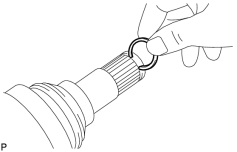
(a) Install a new snap ring to the inboard joint shaft. |
6. INSPECT FRONT DRIVE SHAFT ASSEMBLY


|

|