| Last Modified: 11-27-2007 | 1.6 U | |
| Service Category: Audio/Visual/Telematics | Section: Cellular Communication | |
| Model Year: 2008 | Model: LX570 | Doc ID: RM000001BTW00FX |
| Title: CELLULAR COMMUNICATION: LEXUS LINK SYSTEM: TERMINALS OF ECU (2008 LX570) | ||
TERMINALS OF ECU
1. CHECK TELEPHONE ECU ASSEMBLY
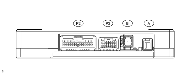
(a) Arrangement of telephone ECU assembly terminal.
|
Terminal No. (Symbol) |
Wiring Color |
Terminal Description |
|---|---|---|
|
P2-1 (+B) |
G |
Vehicle battery power supply |
|
P2-2 (SPO+) |
W |
Audio speaker output + |
|
P2-3 (SPO-) |
B |
Audio speaker output - |
|
P2-7 (MCVD) |
Y |
Microphone power supply |
|
P2-8 (MCI+) |
G |
Microphone input signal + |
|
P2-9 (MCI-) |
R |
Microphone input signal - |
|
P2-10 (SPI+) |
W |
Sound signal |
|
P2-11 (SPI-) |
B |
Sound signal |
|
P2-12 (E) |
W-B |
Ground |
|
P2-13 (IG2) |
B |
IG power supply |
|
P2-14 (ACC) |
GR |
ACC power supply |
|
P2-16 (GSW) |
L |
Airbag signal |
|
P2-17 (MCO+) |
G |
Microphone output |
|
P2-18 (MCO-) |
R |
Audio ground |
|
P2-19 (SGND) |
Shielded |
Shield ground |
|
P2-21 (HFOF) |
B |
Phone mute |
|
P2-22 (MUTE) |
B |
Radio mute |
|
P2-23 (MPX1) |
B |
MPX line |
|
P3-2 (BBI+) |
R |
Mayday battery input |
|
P3-4 (IND1) |
L |
Red LED output |
|
P3-5 (SIG1) |
W |
Mayday switch input |
|
P3-9 (BBI-) |
L |
Mayday battery input |
|
P3-11 (IND2) |
P |
Green LED output |
|
P3-12 (SIG-) |
L |
Mayday switch ground |
|
P3-13 (SIG2) |
W |
Mayday switch input |
|
P3-15 (SIL) |
R |
DLC3 line |
(b) Check telephone ECU assembly.
(1) Disconnect the P2 and P3 ECU connectors.
(2) Measure the resistance and voltage according to the value(s) in the table below.
|
Terminal No. (Symbol) |
Wiring Color |
Terminal Description |
Condition |
Specified Condition |
|---|---|---|---|---|
|
P2-12 (E) - Body ground |
W-B - Body ground |
Ground |
Always |
Below 1 Ω |
|
P2-1 (+B) - Body ground |
G - Body ground |
Vehicle battery power supply |
Always |
11 to 14 V |
|
P2-14 (ACC) - Body ground |
GR - Body ground |
ACC power supply |
Engine switch on (ACC) |
11 to 14 V |
|
P2-13 (IG2) - Body ground |
B - Body ground |
IG power supply |
Engine switch on (IG) |
11 to 14 V |
|
P2-10 (SPI+) - P2-12 (E) |
W - W-B |
Sound signal |
Audio system playing |
Waveform synchronized with sound is output |
|
P2-11 (SPI-) - P2-12 (E) |
B - W-B |
Sound signal |
Audio system playing |
Waveform synchronized with sound is output |
|
P2-21 (HFOF) - P2-12 (E) |
B - W-B |
Phone mute |
Engine switch on (IG) |
3.3 to 5.0 V |
|
P2-22 (MUTE) - P2-12 (E) |
B - W-B |
Radio mute |
Engine switch on (IG) |
3.3 to 5.0 V |
|
P3-2 (BBI+) - P3-9 (BBI-) |
R - L |
Non-rechargeable back-up |
Always |
9 to 16 V |
|
P3-5 (SIG1) - P3-12 (SIG-) |
W - L |
Mayday switch input |
Engine switch off, all buttons not pushed |
4.4 to 5.0 kΩ |
|
P3-13 (SIG2) - P3-12 (SIG-) |
W - L |
Mayday switch input |
Engine switch off, all buttons not pushed |
4.4 to 5.0 kΩ |
If the result is not as specified, there may be a malfunction on the wire harness side.
(3) Disconnect the B telephone antenna (cellular phone) connector (color: blue) from the ECU.
(4) Measure the resistance according to the value(s) in the table below.
|
Terminal No. (Symbol) |
Wiring Color |
Terminal Description |
Condition |
Specified Condition |
|---|---|---|---|---|
|
B-1 (SIGNAL) - Body ground |
B - Body ground |
Telephone signal input/output |
Always |
4 to 11 kΩ |
If the result is not as specified, there may be a malfunction on the antenna side.
2. CHECK BUS BUFFER ECU
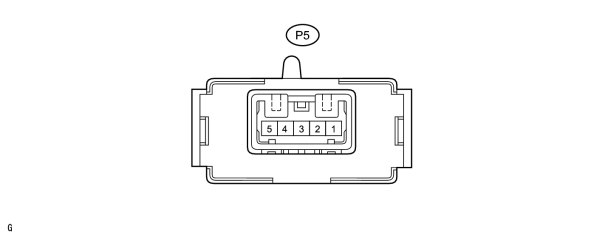
(a) Disconnect the P5 ECU connector.
(b) Measure the resistance and voltage according to the value(s) in the table below.
|
Terminal No. (Symbol) |
Wiring Color |
Terminal Description |
Condition |
Specified Condition |
|---|---|---|---|---|
|
P5-4 (GND) - Body ground |
W-B - Body ground |
Ground |
Always |
Below 1 Ω |
|
P5-3 (+B) - Body ground |
G - Body ground |
Battery power supply |
Always |
11 to 14 V |
If the result is not as specified, there may be a malfunction on the wire harness side.
(c) Reconnect the P5 ECU connector.
(d) Measure the voltage according to the value(s) in the table below.
|
Terminal No. (Symbol) |
Wiring Color |
Terminal Description |
Condition |
Specified Condition |
|---|---|---|---|---|
|
P5-5 (S1) - P5-4 (GND) |
B - W-B |
MPX line |
Always |
Pulse generation |
If the result is not as specified, the ECU may have a malfunction.

|

|