| Last Modified: 11-27-2007 | 1.6 G | |
| Service Category: Vehicle Exterior | Section: Mirror (ext) | |
| Model Year: 2008 | Model: LX570 | Doc ID: RM000001DHF013X |
| Title: MIRROR (EXT): OUTER MIRROR SWITCH: INSPECTION (2008 LX570) | ||
INSPECTION
1. INSPECT OUTER MIRROR SWITCH ASSEMBLY
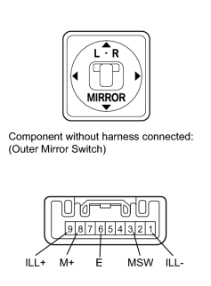
(a) Inspect the mirror control switch.
(1) Select "L" on the left/right adjustment switch.
(2) Measure the resistance according to the value(s) in the table below.
Standard Resistance:
|
Tester Connection |
Switch Condition |
Specified Condition |
|---|---|---|
|
8 (M+) - 6 (E) |
Up switch pushed |
90 to 110 Ω |
|
Down switch pushed |
437 to 502 Ω |
|
|
Left switch pushed |
744 to 856 Ω |
|
|
Right switch pushed |
207 to 253 Ω |
|
|
No switches pushed |
10 kΩ or higher |
|
|
3 (MSW) - 6 (E) |
Adjustment switch in L position |
90 to 110 Ω |
|
Adjustment switch in neutral position |
10 kΩ or higher |
If the result is not as specified, replace the outer mirror switch assembly.
(3) Select "R" on the left/right adjustment switch.
(4) Measure the resistance according to the value(s) in the table below.
Standard Resistance:
|
Tester Connection |
Switch Condition |
Specified Condition |
|---|---|---|
|
8 (M+) - 6 (E) |
Up switch pushed |
90 to 110 Ω |
|
Down switch pushed |
437 to 502 Ω |
|
|
Left switch pushed |
744 to 856 Ω |
|
|
Right switch pushed |
207 to 253 Ω |
|
|
No switches pushed |
10 kΩ or higher |
|
|
3 (MSW) - 6 (E) |
Adjustment switch in R position |
Below 1 Ω |
|
Adjustment switch in neutral position |
10 kΩ or higher |
If the result is not as specified, replace the outer mirror switch assembly.
(5) Inspect the switch illumination.
Apply battery voltage between the terminals of the light, and check the operation of the light.
OK:
|
Measurement Condition |
Specified Condition |
|---|---|
|
Battery positive (+) → Terminal 9 (ILL+) Battery negative (-) → Terminal 1 (ILL-) |
Light comes on |
If the result is not as specified, replace the outer mirror switch assembly.
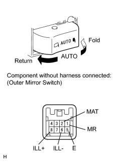
|
(b) Inspect the mirror retract switch. (1) Measure the resistance according to the value(s) in the table below. Standard Resistance:
If the result is not as specified, replace the outer mirror switch assembly. (2) Inspect the switch illumination. Apply battery voltage between the terminals of the light, and check the operation of the light. OK:
If the result is not as specified, replace the outer mirror switch assembly. |

|

|