- Stop light switch
- Harness or connector
- Master cylinder solenoid (Skid control ECU)
| Last Modified: 11-27-2007 | 1.6 C | |
| Service Category: Brake | Section: Brake Control/Dynamic Control System | |
| Model Year: 2008 | Model: LX570 | Doc ID: RM000001DXC00JX |
| Title: BRAKE CONTROL / DYNAMIC CONTROL SYSTEMS: VEHICLE STABILITY CONTROL SYSTEM: DESCRIPTION (2008 LX570) | ||
|
DTC |
C1249/49 |
Open in Stop Light Switch Circuit |
DESCRIPTION
The stop light switch signal is input to the skid control ECU and the skid control ECU detects the status of brake operation.
The skid control ECU has an open detection circuit.
If an open in the stop light switch input line or GND side stop light circuit is detected when the stop light switch is off, this DTC is stored.
|
DTC Code |
DTC Detection Condition |
Trouble Area |
|---|---|---|
|
C1249/49 |
The ECU terminal IG1 voltage is 9.5 to 17.0 V, ABS is not operating, and an open in the stop light switch circuit continues for 3 seconds or more. |
|
WIRING DIAGRAM
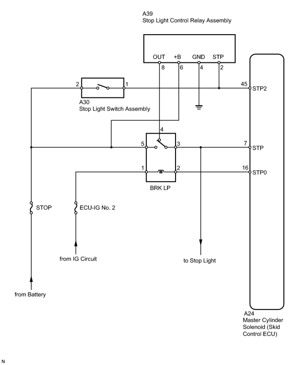
INSPECTION PROCEDURE
NOTICE:
When replacing the master cylinder solenoid, perform zero point calibration
 .
.
PROCEDURE
|
1. |
CHECK STOP LIGHT SWITCH OPERATION |
(a) Check that the stop light comes on when the brake pedal is depressed, and goes off when the brake pedal is released.
OK:
Stop light switch function is normal.
|

|
2. |
INSPECT SKID CONTROL ECU (STP TERMINAL) |
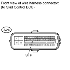
|
(a) Disconnect the A24 skid control ECU connector. |
(b) Measure the voltage according to the value(s) in the table below.
Standard Voltage:
|
Tester Connection |
Switch Condition |
Specified Condition |
|---|---|---|
|
A24-7 (STP) - Body ground |
Stop light switch on (Brake pedal depressed) |
8 to 14 V |
|
A24-7 (STP) - Body ground |
Stop light switch off (Brake pedal released) |
Below 1.5 V |
Result
|
Result |
Proceed to |
|---|---|
|
OK (When troubleshooting in accordance with the Diagnostic Trouble Code Chart) |
A |
|
OK (When troubleshooting in accordance with the Problem Symptoms Table) |
B |
|
NG |
C |
|
|
3. |
RECONFIRM DTC |
(a) Clear the DTC
.
(b) Check if the same DTC is output
.
HINT:
Reinstall the sensors, connectors, etc. and restore the previous vehicle conditions before rechecking for DTCs.
Result
|
Result |
Proceed to |
|---|---|
|
DTC is output. |
A |
|
DTC is not output. |
B |
|
|
4. |
INSPECT STOP LIGHT SWITCH ASSEMBLY (POWER SOURCE TERMINAL) |
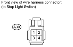
|
(a) Disconnect the A30 stop light switch connector. |
(b) Measure the voltage according to the value(s) in the table below.
Standard Voltage:
|
Tester Connection |
Condition |
Specified Condition |
|---|---|---|
|
A30-2 - Body ground |
Always |
11 to 14 V |
|
|
5. |
INSPECT STOP LIGHT SWITCH ASSEMBLY |
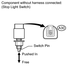
|
(a) Measure the resistance according to the value(s) in the table below. Standard Resistance:
|
|
|
6. |
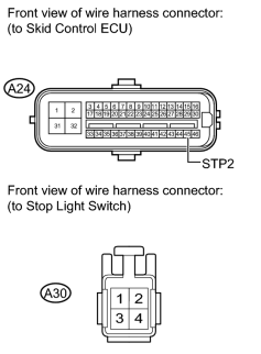
CHECK HARNESS AND CONNECTOR (SKID CONTROL ECU - STOP LIGHT SWITCH) |
|
(a) Disconnect the A24 skid control ECU connector. |
(b) Measure the resistance according to the value(s) in the table below.
Standard Resistance:
|
Tester Connection |
Condition |
Specified Condition |
|---|---|---|
|
A24-45 (STP2) - A30-1 |
Always |
Below 1 Ω |
HINT:
-
When troubleshooting in accordance with the Diagnostic Trouble Code Chart, check DTCs before replacing the master cylinder solenoid
.
-
When troubleshooting in accordance with the Problem Symptoms Table, be sure to follow the table before replacing the master cylinder solenoid
.
|

|

|