- Steering angle sensor
- Harness or connector
- Steering angle sensor power supply
- CAN communication system
- Master cylinder solenoid (Skid control ECU)
| Last Modified: 11-27-2007 | 1.6 C | |
| Service Category: Brake | Section: Brake Control/Dynamic Control System | |
| Model Year: 2008 | Model: LX570 | Doc ID: RM000001DXJ00JX |
| Title: BRAKE CONTROL / DYNAMIC CONTROL SYSTEMS: VEHICLE STABILITY CONTROL SYSTEM: DESCRIPTION (2008 LX570) | ||
|
DTC |
C1231/31 |
Steering Angle Sensor Circuit Malfunction |
DESCRIPTION
The steering angle sensor signal is sent to the skid control ECU through the CAN communication system. When there is a malfunction in the communication system, it will be detected by the diagnosis function.
|
DTC Code |
DTC Detection Condition |
Trouble Area |
|---|---|---|
|
C1231/31 |
When the ECU IG1 terminal voltage is 9.5 V or higher, the steering angle sensor malfunction signal is received. |
|
WIRING DIAGRAM
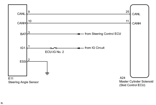
INSPECTION PROCEDURE
NOTICE:
When replacing the master cylinder solenoid, perform zero point calibration
 .
.
HINT:
- When U0073/94, U0100/65, U0114/38, U0123/62, U0124/95, U0126/63 or U0130/68 is output together with C1231/31, inspect and repair the trouble areas indicated by U0073/94, U0100/65, U0114/38, U0123/62, U0124/95, U0126/63 or U0130/68 first.
- When the speed sensor or the yaw rate and G sensor has trouble, DTCs of the steering angle sensor may be stored even when the steering angle sensor is normal. When DTCs of the speed sensor (C0200/31, C0205/32, C0210/33, C0215/34, C1235/35, C1236/36, C1238/38, C1239/39) or yaw rate and G sensor (C1232/32, C1234/34, C1243/43, C1244/44, C1245/45, C1381/97) are output together with DTCs of the steering angle sensor, inspect and repair the speed sensor and yaw rate and G sensor first, and then inspect and repair the steering angle sensor.
PROCEDURE
|
1. |
READ VALUE USING TECHSTREAM (STEERING ANGLE SENSOR) |
(a) Connect the Techstream to the DLC3.
(b) Turn the engine switch on (IG) and turn the Techstream on.
(c) Enter the following menus: Chassis / ABS/VSC/TRAC / Data List.
ABS/VSC/TRAC
|
Tester Display |
Measurement Item/Range |
Normal Condition |
Diagnostic Note |
|---|---|---|---|
|
Steering Angle Sensor |
Steering angle sensor/min.: -3276.8 degrees, max.: 3276.7 degrees |
Left turn: Increase Right turn: Decrease |
- |
(d) Check that the steering wheel turning angle value of the steering angle sensor displayed on the Techstream changes when turning the steering wheel.
OK:
Steering angle sensor value changes.
|

|
2. |
RECONFIRM DTC |
(a) Clear the DTCs
.
(b) Drive the vehicle at a speed of approximately 10 km/h (6 mph) or more for 10 seconds or more.
(c) Check if the same DTCs are output
.
Result
|
Result |
Proceed to |
|---|---|
|
DTC is output. |
A |
|
DTC is not output. |
B |
|
|
3. |
CHECK HARNESS AND CONNECTOR (STEERING ANGLE SENSOR - BATTERY AND BODY GROUND) |
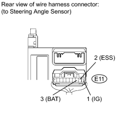
|
(a) Remove the steering wheel and the lower steering column cover. |
(b) Disconnect the E11 steering angle sensor connector.
(c) Measure the voltage according to the value(s) in the table below.
Standard Voltage:
|
Tester Connection |
Switch Condition |
Specified Condition |
|---|---|---|
|
E11-1 (IG1) - Body ground |
Engine switch on (IG) |
11 to 14 V |
|
E11-3 (BAT) - Body ground |
Always |
11 to 14 V |
(d) Measure the resistance according to the value(s) in the table below.
Standard Resistance:
|
Tester Connection |
Condition |
Specified Condition |
|---|---|---|
|
E11-2 (ESS) - Body ground |
Always |
Below 1 Ω |
HINT:
-
When troubleshooting in accordance with the Diagnostic Trouble Code Chart, check DTCs before replacing the steering angle sensor
.
-
When troubleshooting in accordance with the Problem Symptoms Table, be sure to follow the table before replacing the steering angle sensor
.
|

|

|