- The fluid level of the reservoir is LOW for 4 seconds, or 40 seconds after the engine switch is turned on (IG), or for 7 seconds during pump motor operation.
- With the ECU terminal IG1 voltage at 9.5 V to 17.0 V, an open in the brake fluid level warning switch circuit continues for 2 seconds or more.
| Last Modified: 11-27-2007 | 1.6 C | |
| Service Category: Brake | Section: Brake Control/Dynamic Control System | |
| Model Year: 2008 | Model: LX570 | Doc ID: RM000001DXM00IX |
| Title: BRAKE CONTROL / DYNAMIC CONTROL SYSTEMS: VEHICLE STABILITY CONTROL SYSTEM: DESCRIPTION (2008 LX570) | ||
|
DTC |
C1202/58 |
Brake Fluid Level Low / Open Circuit in Brake Fluid Level Warning Switch Circuit |
DESCRIPTION
The brake fluid level warning switch sends the appropriate signal to the skid control ECU when the brake fluid level drops.
|
DTC Code |
DTC Detection Condition |
Trouble Area |
|---|---|---|
|
C1202/58 |
When either of the following conditions is detected: |
|
WIRING DIAGRAM
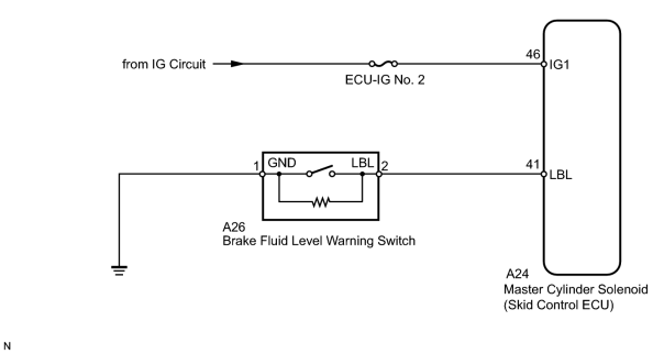
INSPECTION PROCEDURE
NOTICE:
When replacing the master cylinder solenoid, perform zero point calibration
 .
.
HINT:
When C1241/41 is output together with C1202/58, inspect and repair the trouble areas indicated by C1241/41 first.
PROCEDURE
|
1. |
CHECK BRAKE FLUID LEVEL |
(a) Turn the engine switch off.
(b) Depress the brake pedal 20 times or more (until the pedal reaction feels light and pedal stroke becomes longer).
(c) Check the amount of fluid in the brake reservoir.
HINT:
When the engine switch is turned on (IG), brake fluid is sent to the accumulator and the fluid level decreases by approximately 10 mm (0.394 in.) from the level when the engine switch is off (normal).
OK:
Brake fluid level is normal.
|

|
2. |
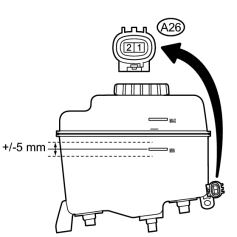
INSPECT BRAKE FLUID LEVEL WARNING SWITCH |
|
(a) Disconnect the A26 brake fluid level warning switch connector. |
(b) Measure the resistance according to the value(s) in the table below.
HINT:
- A float is placed inside the reservoir. Its position can be changed by increasing/decreasing the level of brake fluid.
- The warning switch is switched on/off at +/-5 mm (+/-0.197 in.) from the MIN level.
Standard Resistance:
|
Tester Connection |
Condition |
Specified Condition |
|---|---|---|
|
A26-1 - A26-2 |
Float UP (Switch off) |
1.9 to 2.1 kΩ |
|
A26-1 - A26-2 |
Float DOWN (Switch on) |
Below 1 Ω |
HINT:
If there is no problem after finishing the above check, adjust the brake fluid level to the MAX level.
|
|
3. |
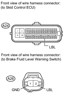
CHECK HARNESS AND CONNECTOR (BRAKE FLUID LEVEL WARNING SWITCH - SKID CONTROL ECU) |
|
(a) Disconnect the A24 skid control ECU connector and A26 brake fluid level warning switch connector. |
(b) Measure the resistance according to the value(s) in the table below.
Standard Resistance:
|
Tester Connection |
Condition |
Specified Condition |
|---|---|---|
|
A24-41 (LBL) - A26-2 (LBL) |
Always |
Below 1 Ω |
|
A24-41 (LBL) - Body ground |
Always |
10 kΩ or higher |
|
A26-1 (GND) - Body ground |
Always |
Below 1 Ω |
|
|
4. |
RECONFIRM DTC |
(a) Clear the DTC
.
(b) Drive the vehicle at a speed of approximately 32 km/h (20 mph) or more for 60 seconds or more.
(c) Check if the same DTC is output
.
HINT:
Reinstall the sensors, connectors, etc. and restore the previous vehicle conditions before rechecking for DTCs.
Result
|
Result |
Proceed to |
|---|---|
|
DTC is output. |
A |
|
DTC is not output. |
B |
|

|

|