| Last Modified: 11-27-2007 | 1.6 J | |
| Service Category: Brake | Section: Brake Control/Dynamic Control System | |
| Model Year: 2008 | Model: LX570 | Doc ID: RM000001DXV00JX |
| Title: BRAKE CONTROL / DYNAMIC CONTROL SYSTEMS: VEHICLE STABILITY CONTROL SYSTEM: DESCRIPTION (2008 LX570) | ||
|
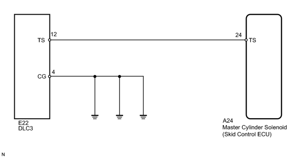
TS and CG Terminal Circuit |
DESCRIPTION
The signal check circuit detects trouble in the sensor or switch signal which cannot be detected by the DTC check.
Connecting terminals TS and CG of the DLC3 starts the check.
WIRING DIAGRAM
INSPECTION PROCEDURE
NOTICE:
When replacing the master cylinder solenoid, perform zero point calibration
 .
.
PROCEDURE
|
1. |
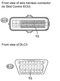
CHECK HARNESS AND CONNECTOR (SKID CONTROL ECU - DLC3 (TS)) |
|
(a) Turn the engine switch off. |
(b) Disconnect the A24 skid control ECU connector.
(c) Measure the resistance according to the value(s) in the table below.
Standard Resistance:
|
Tester Connection |
Condition |
Specified condition |
|---|---|---|
|
A24-24 (TS) - E22-12 (TS) |
Always |
Below 1 Ω |
|

|
2. |
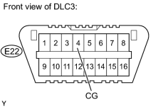
CHECK HARNESS AND CONNECTOR (DLC3 (CG) - BODY GROUND) |
|
(a) Measure the resistance according to the value(s) in the table below. Standard Resistance:
|
|
|
3. |
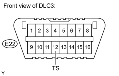
CHECK HARNESS AND CONNECTOR (DLC3 (TS) - BODY GROUND) |
|
(a) Measure the resistance according to the value(s) in the table below. Standard Resistance:
|
|

|

|