- The vehicle speed is more than 3 km/h (2 mph).
- The IG1 terminal voltage is below 9.5 V.
| Last Modified: 11-27-2007 | 1.6 C | |
| Service Category: Brake | Section: Brake Control/Dynamic Control System | |
| Model Year: 2008 | Model: LX570 | Doc ID: RM000001DXW00JX |
| Title: BRAKE CONTROL / DYNAMIC CONTROL SYSTEMS: VEHICLE STABILITY CONTROL SYSTEM: DESCRIPTION (2008 LX570) | ||
|
DTC |
C1241/41 |
Low Battery Positive Voltage |
DESCRIPTION
If the voltage supplied to the IG1 terminal is within the DTC detection range due to malfunctions in components such as the battery and alternator circuit, this DTC is stored.
|
DTC Code |
DTC Detection Condition |
Trouble Area |
|---|---|---|
|
C1241/41 |
When either of the following conditions is detected: 1. Both of the following conditions continue for at least 10 seconds. 2. All of the following conditions continue for at least 0.2 seconds.
|
|
WIRING DIAGRAM
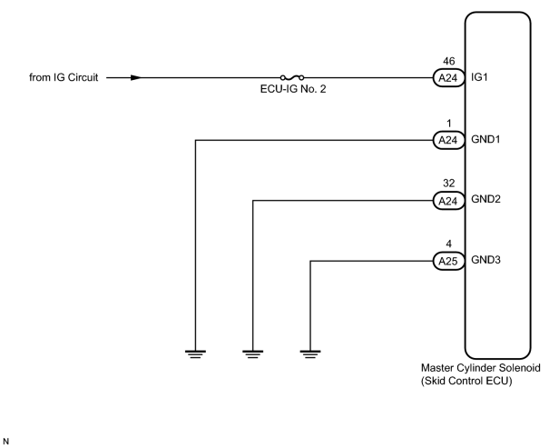
INSPECTION PROCEDURE
NOTICE:
When replacing the master cylinder solenoid, perform zero point calibration
 .
.
PROCEDURE
|
1. |
INSPECT BATTERY |
(a) Check the battery voltage.
Standard Voltage:
11 to 14 V
|

|
2. |
INSPECT ECU-IG NO. 2 FUSE |
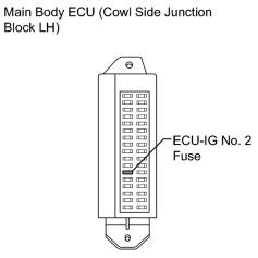
|
(a) Remove the ECU-IG No. 2 fuse from the main body ECU (cowl side junction block LH). |
(b) Measure the resistance according to the value(s) in the table below.
Standard Resistance:
|
Tester Connection |
Condition |
Specified Condition |
|---|---|---|
|
ECU-IG No. 2 fuse |
Always |
Below 1 Ω |
|
|
3. |
READ VALUE USING TECHSTREAM (IG1 VOLTAGE VALUE) |
(a) Install the ECU-IG No. 2 fuse.
(b) Connect the Techstream to the DLC3.
(c) Turn the engine switch on (IG) and turn the Techstream on.
(d) Start the engine.
(e) Enter the following menus: Chassis / ABS/VSC/TRAC / Data List.
ABS/VSC/TRAC
|
Tester Display |
Measurement Item/Range |
Normal Condition |
Diagnostic Note |
|---|---|---|---|
|
IG1 Voltage Value |
IG1 voltage value/min.: 0 V, max.: 255 V |
9.5 to 14.0 V |
- |
(f) Measure the voltage output from the skid control ECU displayed on the Techstream.
OK:
The output voltage displayed on the Techstream is within 9.5 to 14.0 V.
|
|
4. |
RECONFIRM DTC |
(a) Clear the DTCs
.
(b) Check if the same DTCs are output
.
HINT:
Reinstall the sensors, connectors, etc. and restore the previous vehicle conditions before rechecking for DTCs.
Result
|
Result |
Proceed to |
|---|---|
|
DTC is output. |
A |
|
DTC is not output (When troubleshooting in accordance with the Diagnostic Trouble Code Chart). |
B |
|
DTC is not output (When troubleshooting in accordance with the Problem Symptoms Table). |
C |
|
|
5. |
INSPECT SKID CONTROL ECU (IG1 TERMINAL) |
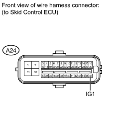
|
(a) Disconnect the A24 skid control ECU connector. |
(b) Measure the voltage according to the value(s) in the table below.
Standard Voltage:
|
Tester Connection |
Switch Condition |
Specified Condition |
|---|---|---|
|
A24-46 (IG1) - Body ground |
Engine switch on (IG) |
11 to 14 V |
|
|
6. |
INSPECT SKID CONTROL ECU (GND TERMINAL) |
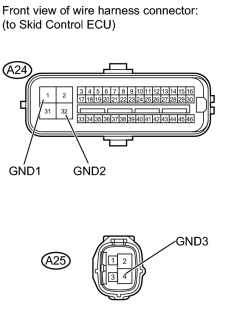
|
(a) Disconnect the A24 and A25 skid control ECU connectors. |
(b) Measure the resistance according to the value(s) in the table below.
Standard Resistance:
|
Tester Connection |
Condition |
Specified Condition |
|---|---|---|
|
A24-1 (GND1) - Body ground |
Always |
Below 1 Ω |
|
A24-32 (GND2) - Body ground |
Always |
Below 1 Ω |
|
A25-4 (GND3) - Body ground |
Always |
Below 1 Ω |
|
|
7. |
RECONFIRM DTC |
(a) Clear the DTCs
.
(b) Check if the same DTCs are output
.
HINT:
Reinstall the sensors, connectors, etc. and restore the previous vehicle conditions before rechecking for DTCs.
Result
|
Result |
Proceed to |
|---|---|
|
DTC is output. |
A |
|
DTC is not output (When troubleshooting in accordance with the Diagnostic Trouble Code Chart). |
B |
|
DTC is not output (When troubleshooting in accordance with the Problem Symptoms Table). |
C |
|

|

|