- Yaw rate and G sensor
- Harness or connector
- CAN communication system
| Last Modified: 11-27-2007 | 1.6 C | |
| Service Category: Brake | Section: Brake Control/Dynamic Control System | |
| Model Year: 2008 | Model: LX570 | Doc ID: RM000001EA300GX |
| Title: BRAKE CONTROL / DYNAMIC CONTROL SYSTEMS: VEHICLE STABILITY CONTROL SYSTEM: DESCRIPTION (2008 LX570) | ||
|
DTC |
C1232/32 |
Stuck in Deceleration Sensor |
|
DTC |
C1234/34 |
Yaw Rate Sensor Malfunction |
|
DTC |
C1243/43 |
Acceleration Sensor Stuck Malfunction |
|
DTC |
C1244/44 |
Open or Short in Deceleration Sensor Circuit |
|
DTC |
C1245/45 |
Acceleration Sensor Output Malfunction |
|
DTC |
C1381/97 |
Acceleration Sensor Power Supply Voltage Malfunction |
DESCRIPTION
The skid control ECU receives signals from the yaw rate and G sensor via the CAN communication system.
The yaw rate sensor has a built-in G sensor.
If there is trouble in the bus lines between the yaw rate and G sensor and the CAN communication system, the DTCs U0123/62 (yaw rate sensor communication trouble) and U0124/95 (G sensor communication trouble) are stored.
|
DTC Code |
DTC Detection Condition |
Trouble Area |
|---|---|---|
|
C1232/32 |
At a vehicle speed of 10 km/h (6 mph) or more, the fluctuation range of the signal from one of either GL1 or GL2 is below 80 mV and the fluctuation range of the signal of the other is higher than 1.9 V for 30 seconds or more. |
|
|
C1234/34 |
A sensor malfunction signal is received from the yaw rate sensor. |
|
|
C1243/43 |
The following condition repeats 16 times.
|
|
|
C1244/44 |
When either of the following conditions is detected: 1. Both of the following conditions continue for at least 60 seconds.
2. A data malfunction signal is received from the G sensor. |
|
|
C1245/45 |
The following condition continues for at least 60 seconds.
|
|
|
C1381/97 |
A G sensor power source malfunction signal is received for at least 10 seconds at a speed of more than 3 km/h (2 mph). |
|
WIRING DIAGRAM
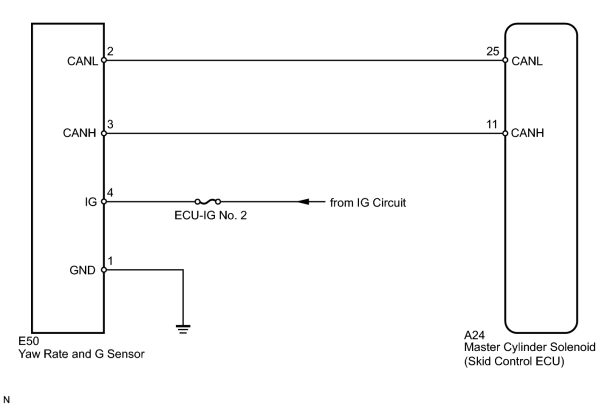
INSPECTION PROCEDURE
NOTICE:
When replacing the yaw rate and G sensor, perform zero point calibration
 .
.
PROCEDURE
|
1. |
CHECK DTC |
(a) Clear the DTCs
.
(b) Turn the engine switch off.
(c) Turn the engine switch on (IG).
(d) Check if the DTCs (U0073/94, U0123/62, C1210/36 and/or C1336/98) are output
.
Result
|
Result |
Proceed to |
|---|---|
|
DTC U0073/94, U0123/62, C1210/36 and/or C1336/98 are not output. |
A |
|
DTC U0073/94 and/or U0123/62 are output. |
B |
|
DTC C1210/36 and/or C1336/98 are output. |
C |
|

|
2. |
CHECK YAW RATE AND G SENSOR INSTALLATION |
(a) Check that the yaw rate and G sensor is installed properly.
OK:
The sensor is tightened to the specified torque. The sensor is not tilted.
|
|
3. |
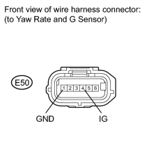
INSPECT YAW RATE AND G SENSOR (IG AND GND TERMINAL) |
|
(a) Disconnect the E50 yaw rate and G sensor connector. |
(b) Measure the voltage according to the value(s) in the table below.
Standard Voltage:
|
Tester Connection |
Switch Condition |
Specified Condition |
|---|---|---|
|
E50-4 (IG) - Body ground |
Engine switch on (IG) |
11 to 14 V |
(c) Measure the resistance according to the value(s) in the table below.
Standard Resistance:
|
Tester Connection |
Condition |
Specified Condition |
|---|---|---|
|
E50-1 (GND) - Body ground |
Always |
Below 1 Ω |
Result
|
Result |
Proceed to |
|---|---|
|
OK (When troubleshooting in accordance with the Diagnostic Trouble Code Chart) |
A |
|
OK (When troubleshooting in accordance with the Problem Symptoms Table) |
B |
|
NG |
C |
|

|

|