- Telephone ECU assembly
- Map light assembly (Mayday switch)
- Harness or connector
| Last Modified: 11-27-2007 | 1.6 C | |
| Service Category: Audio/Visual/Telematics | Section: Cellular Communication | |
| Model Year: 2008 | Model: LX570 | Doc ID: RM000001EG500DX |
| Title: CELLULAR COMMUNICATION: LEXUS LINK SYSTEM: DESCRIPTION (2008 LX570) | ||
|
DTC |
4-7 |
EMERGENCY, VOL+ or VOL- Button has Connection Error |
DESCRIPTION
This DTC is stored when one of the following occurs: 1) the telephone ECU assembly is malfunctioning; 2) the mayday switch on the map light assembly is malfunctioning; or 3) the wire harness between the telephone ECU assembly and the map light is open.
|
DTC Code |
DTC Detection Condition |
Trouble Area |
|---|---|---|
|
4-7 |
Communication or the communication line is abnormal between the telephone ECU assembly and map light (mayday switch). |
|
WIRING DIAGRAM
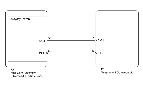
INSPECTION PROCEDURE
PROCEDURE
|
1. |
CHECK HARNESS AND CONNECTOR (TELEPHONE ECU ASSEMBLY - MAP LIGHT ASSEMBLY) |
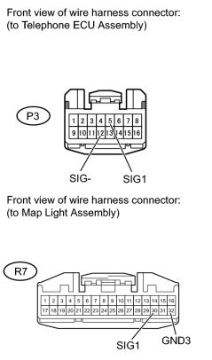
(a) Disconnect the P3 ECU connector.
(b) Disconnect the R7 map light connector.
(c) Measure the resistance according to the value(s) in the table below.
Standard Resistance:
|
Tester Connection |
Condition |
Specified Condition |
|---|---|---|
|
P3-5 (SIG1) - R7-30 (SIG1) |
Always |
Below 1 Ω |
|
P3-12 (SIG-) - R7-32 (GND3) |
Always |
Below 1 Ω |
|

|
2. |
INSPECT MAP LIGHT ASSEMBLY (MAYDAY SWITCH) |
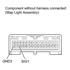
(a) Remove the map light
 .
.
(b) Measure the resistance according to the value(s) in the table below.
Standard Resistance:
|
Tester Connection |
Condition |
Specified Condition |
|---|---|---|
|
30 (SIG1) - 32 (GND3) |
Emergency button is pressed |
305 to 313 Ω |
|
30 (SIG1) - 32 (GND3) |
VOL+ button is pressed |
812 to 831 Ω |
|
30 (SIG1) - 32 (GND3) |
VOL- button is pressed |
1811 to 1848 Ω |
|
|
3. |
REPLACE TELEPHONE ECU ASSEMBLY TOGETHER WITH MAYDAY BATTERY |
|

|

|