- Telephone ECU assembly
- Center airbag sensor assembly
- Harness or connector
| Last Modified: 11-27-2007 | 1.6 C | |
| Service Category: Audio/Visual/Telematics | Section: Cellular Communication | |
| Model Year: 2008 | Model: LX570 | Doc ID: RM000001EG700DX |
| Title: CELLULAR COMMUNICATION: LEXUS LINK SYSTEM: DESCRIPTION (2008 LX570) | ||
|
DTC |
5-2 |
Airbag Signal Communication Error |
DESCRIPTION
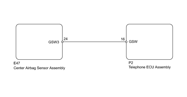
This DTC is stored when one of the following occurs: 1) the telephone ECU assembly is malfunctioning; 2) the center airbag sensor is malfunctioning; or 3) the communication line is open or shorted.
|
DTC Code |
DTC Detection Condition |
Trouble Area |
|---|---|---|
|
5-2 |
Communication or the communication line is abnormal between the telephone ECU assembly and center airbag sensor. |
|
WIRING DIAGRAM
INSPECTION PROCEDURE
PROCEDURE
|
1. |
CHECK FOR DTC (BLINKING PATTERN) |
(a) Turn the engine switch from on (IG) to off.
(b) Turn the engine switch on (IG) and wait for 10 seconds.
(c) Check for the DTC again and wait for 20 seconds
 .
.
OK:
DTC 5-2 is not output.
|

|
2. |
CHECK SUPPLEMENTAL RESTRAINT SYSTEM |
(a) Check for DTC using the Techstream
.
Result
|
Result |
Proceed to |
|---|---|
|
DTC related to supplemental restraint system output |
A |
|
No DTC output |
B |
|
|
3. |
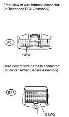
CHECK HARNESS AND CONNECTOR (TELEPHONE ECU ASSEMBLY - CENTER AIRBAG SENSOR) |
(a) Disconnect the cable from the negative (-) battery terminal and wait for 90 seconds.
CAUTION:
Wait at least 90 seconds after disconnecting the cable from the negative (-) battery terminal to disable the SRS system.
NOTICE:
- After the engine switch is turned off, the HDD navigation system requires approximately 6 minutes to record various types of memory and settings. As a result, after turning the engine switch off, wait 6 minutes or more before disconnecting the cable from the negative (-) battery terminal.
-
When disconnecting the cable, some systems need to be initialized after the cable is reconnected
.
(b) Disconnect the P2 ECU connector.
(c) Disconnect the E47 airbag sensor connector.
(d) Measure the resistance according to the value(s) in the table below.
Standard Resistance:
|
Tester Connection |
Condition |
Specified Condition |
|---|---|---|
|
P2-16 (GSW) - E47-24 (GSW3) |
Always |
Below 1 Ω |
|
P2-16 (GSW) or E47-24 (GSW3) - Body ground |
Always |
10 kΩ or higher |
|
|
4. |
REPLACE TELEPHONE ECU ASSEMBLY TOGETHER WITH MAYDAY BATTERY |
|

|

|