| Last Modified: 11-27-2007 | 1.6 J | |
| Service Category: Audio/Visual/Telematics | Section: Cellular Communication | |
| Model Year: 2008 | Model: LX570 | Doc ID: RM000001FHT00DX |
| Title: CELLULAR COMMUNICATION: LEXUS LINK SYSTEM: DESCRIPTION (2008 LX570) | ||
|
ECU Power Source Circuit |
DESCRIPTION
This circuit supplies power to operate the telephone ECU assembly.
WIRING DIAGRAM
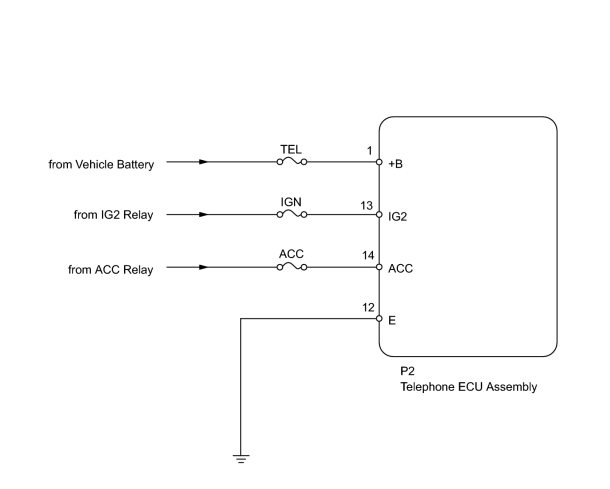
INSPECTION PROCEDURE
PROCEDURE
|
1. |
INSPECT FUSE (TEL, IGN, ACC) |
(a) Remove the TEL and IGN fuses from the engine room relay block.
(b) Remove the ACC fuse from the cowl side junction block LH.
(c) Measure the resistance according to the value(s) in the table below.
Standard Resistance:
|
Tester Connection |
Condition |
Specified Condition |
|---|---|---|
|
TEL fuse |
Always |
Below 1 Ω |
|
IGN fuse |
Always |
Below 1 Ω |
|
ACC fuse |
Always |
Below 1 Ω |
|

|
2. |
CHECK HARNESS AND CONNECTOR (ECU - VEHICLE BATTERY AND BODY GROUND) |
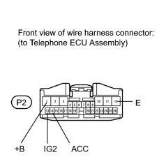
|
(a) Disconnect the P2 ECU connector. |
(b) Measure the voltage and resistance according to the value(s) in the table below.
Standard Voltage:
|
Tester Connection |
Switch Condition |
Specified Condition |
|---|---|---|
|
P2-1 (+B) - Body ground |
Always |
11 to 14 V |
|
P2-13 (IG2) - Body ground |
Engine switch on (IG) |
11 to 14 V |
|
Engine switch off |
Below 1 V |
|
|
P2-14 (ACC) - Body ground |
Engine switch on (ACC) |
11 to 14 V |
|
Engine switch off |
Below 1 V |
Standard Resistance:
|
Tester Connection |
Condition |
Specified Condition |
|---|---|---|
|
P2-12 (E) - Body ground |
Always |
Below 1 Ω |
|
|
3. |
REPLACE TELEPHONE ECU ASSEMBLY TOGETHER WITH MAYDAY BATTERY |
|

|

|