| Last Modified: 11-27-2007 | 1.6 D | |
| Service Category: Power Source/Network | Section: Networking | |
| Model Year: 2008 | Model: LX570 | Doc ID: RM000001RSO00ZX |
| Title: NETWORKING: CAN COMMUNICATION SYSTEM: HOW TO PROCEED WITH TROUBLESHOOTING (2008 LX570) | ||
HOW TO PROCEED WITH TROUBLESHOOTING
Disconnect the cable from the negative (-) battery terminal before measuring the resistances of the main wire and the branch wire.
CAUTION:
Wait at least 90 seconds after disconnecting the cable from the negative (-) battery terminal to disable the SRS system.
NOTICE:
- DTCs for the CAN communication system are as follows: U0073, U0100, U0101, U0114/38, U0122, U0123, U0124, U0126, U0127, U0129, U0130, U0132, U0140, U0141, U0148, U0151, U0199, U0208, U0230, U0327, U1002 (CAN MS BUS), U1002 (CAN No. 2 BUS), U1100, U1101, U1111, U1115, U1126, B1499, B2427, B2621, B2624 and C2179.
- Refer to the troubleshooting procedures of each system if DTCs regarding the CAN communication system are not output.
- Before measuring the resistance, leave the vehicle for at least 1 minute and do not operate the engine switch, any switches or doors. If doors need to be opened in order to check connectors, open the doors and leave them open.
-
w/ Navigation System:
After the engine switch is turned off, the HDD navigation system requires approximately 6 minutes to record various types of memory and settings. As a result, after turning the engine switch off, wait 6 minutes or more before disconnecting the cable from the negative (-) battery terminal.
-
When disconnecting the cable, some systems need to be initialized after the cable is reconnected
 .
.
HINT:
- Operating the engine switch, any switches or any doors triggers related ECU and sensor communication with the CAN, which causes resistance variation.
- *: Use the Techstream.
|
1. |
VEHICLE BROUGHT TO WORKSHOP |
|

|
2. |
INSPECT BATTERY VOLTAGE |
Standard voltage:
11 to 14 V
If the voltage is below 11 V, recharge or replace the battery before proceeding.
|
|
3. |
CHECK AND CLEAR DTC* |
(a) Using the Techstream, perform the Health Check (all DTCs check).
NOTICE:
- If there is a CAN communication trouble code that indicates that an ECU or sensor has a power malfunction or interior malfunction which is causing a communication stop, the problem may not be in the communication line.
- When CAN communication related connectors are disconnected with the engine switch on (IG) or on (ACC), the ECU related to the connector and ECUs of related systems will store a CAN communication DTC.
|
|
4. |
CHECK INSTALLED SYSTEMS (ECU AND SENSOR) THAT USE CAN COMMUNICATION |
(a) Based on the vehicle equipment and specifications, confirm the systems that use CAN communication
.
|
|
5. |
CHECK DLC3 BRANCH WIRE AND V BUS CIRCUIT MAIN WIRE (CANH - CANL) |
(a) Disconnect the cable from the negative (-) battery terminal before measuring the resistances of the main wire and the branch wire.
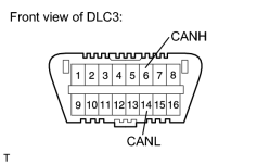
|
(b) Measure the resistance of the DLC3. Standard Resistance:
|
| B |

|
Go to CAN MAIN WIRE FOR DISCONNECTION |
| C |
|
Go to CHECK CAN BUS LINES FOR SHORT CIRCUIT |
|
|
6. |
CHECK V BUS CIRCUIT +B (CANH, CANL - BAT) |
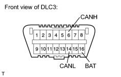
|
(a) Measure the resistance of the DLC3. Standard Resistance:
|
| NG |
|
Go to CHECK CAN BUS LINE FOR SHORT TO +B |
|
|
7. |
CHECK V BUS CIRCUIT GND (CANH, CANL - CG) |
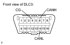
|
(a) Measure the resistance of the DLC3. Standard Resistance:
|
| NG |
|
Go to CHECK CAN BUS LINE FOR SHORT TO GND |
|
|
8. |
CHECK ECUS CONNECTED TO CAN BUS* |
(a) Connect the cable to the negative (-) battery terminal.
NOTICE:
When disconnecting the cable, some systems need to be initialized after the cable is reconnected
.
(b) Select "CAN Bus Check" from "System Select".
(c) Wait 1 minute and then check the display of the connected ECUs and sensors.
Result
|
Inspection Result |
Proceed to |
|---|---|
|
All ECUs and sensors connected to the CAN communication system are displayed on the screen. |
A |
|
Except for the main body ECU (cowl side junction block LH), no ECUs connected to the MS bus are displayed. The main body ECU (cowl side junction block LH) outputs the MS bus trouble code (U1002) (the MS bus main wire open or short malfunction). |
B |
|
No ECUs connected to the MS bus are displayed (the branch wire between the main body ECU (cowl side junction block LH) and V bus circuit is open). |
C |
|
Except for the network gateway ECU, no ECUs connected to the movement control bus are displayed. The network gateway ECU outputs the movement control bus trouble code (U1002) (the movement control bus main wire open or short malfunction). |
D |
|
No ECUs connected to the movement control bus are displayed (the branch wire between the network gateway ECU and movement control bus is open). |
E |
|
An ECU or sensor that should be connected to the CAN communication system is not displayed (the ECU or sensor branch wire is open). |
F |
|
An ECU or sensor that should be connected to the CAN communication system is not displayed or display is intermittent during check (the ECU or sensor branch wire is open on one side). |
G |
NOTICE:
The ECUs and sensors that are not present will not be displayed. Be careful not to mistake them for communication stop malfunctions.
HINT:
- If the display of an ECU is intermittent during the check, one side of an ECU or sensor branch wire is open (The signal of the ECU is treated as noise, which affects the response and display of the Techstream).
- The main body ECU (cowl side junction block LH) checks for proper ECU communication for ECUs that are connected to the CAN MS bus circuit, and the results are displayed on the Techstream.
- The gateway ECU built into the main body ECU (cowl side junction block LH) may be malfunctioning if both of the following occurs: 1) all ECUs connected to the MS bus are not displayed on the Techstream; and 2) DTC U1002 is not output.
- If communication stops between an ECU and the main body ECU (cowl side junction block LH) or network gateway ECU for 10 seconds or more, the ECU disappears from the Techstream display.
- For communication stop mode of ECUs connected to the CAN MS bus circuit or movement control bus, refer to the DTC flowchart of the respective communication stop.
| B |
|
Go to DTC U1002 FLOWCHART |
| C |
|
Go to MAIN BODY ECU COMMUNICATION STOP MODE FLOWCHART |
| D |
|
Go to DTC U1002 FLOWCHART |
| E |
|
Go to NETWORK GATEWAY ECU COMMUNICATION STOP MODE FLOWCHART |
| F |
|
Go to PROBLEM SYMPTOMS TABLE |
| G |
|
Go to OPEN IN ONE SIDE OF CAN BRANCH WIRE FLOWCHART |
|
|
9. |
CHECK COMMUNICATION MALFUNCTION DTC (PAST DTC CHECK)* |
(a) Select "CAN Bus Check" from "System Select".
(b) Write down all of the DTCs stored in each ECU.
HINT:
- If there are communication malfunction DTCs stored but the Techstream "CAN Bus Check - Communication Bus Check" screen displays all of the ECUs and sensors connected to the CAN system, the communication malfunction DTCs may be past malfunctions that are no longer present.
- For V bus main wire malfunctions, related ECUs are also detected. Therefore, determine the malfunctioning area based on all of the DTCs that are output.
- For MS bus malfunctions, DTCs are stored based on the detection of communication stop malfunctions and network malfunctions of ECUs that are connected by the main body ECU (cowl side junction block LH).
- For movement control bus malfunctions, DTCs are stored based on the detection of communication stop malfunctions and network malfunctions of ECUs that are connected by the network gateway ECU.
Result
|
Inspection Result |
Proceed to |
|---|---|
|
An ECU connected to the V bus main wire has stored a communication trouble code (V bus main wire past malfunction). |
A |
|
The main body ECU (cowl side junction block LH) outputs the MS bus trouble code (U1002) (MS bus past malfunction). |
B |
|
The main body ECU (cowl side junction block LH) outputs a trouble code other than MS bus trouble code (U1002) (past malfunction of ECU branch wire connected to MS bus). |
C |
|
The network gateway ECU outputs the movement control bus trouble code (U1002) (movement control bus past malfunction). |
D |
|
The network gateway ECU outputs a trouble code other than movement control bus trouble code (U1002) (past malfunction of branch wire connected to movement control bus). |
E |
| B |
|
Go to DTC U1002 FLOWCHART |
| C |
|
Go to PROBLEM SYMPTOMS TABLE |
| D |
|
Go to DTC U1002 FLOWCHART |
| E |
|
Go to PROBLEM SYMPTOMS TABLE |
|
|
10. |
CHECK DTC COMBINATION TABLE (V BUS CIRCUIT BRANCH WIRE OPEN PAST MALFUNCTION) |
(a) Based on the combination of stored CAN communication system DTCs, determine which ECUs and sensors have a communication stop malfunction
.
|
|
11. |
PERFORM MALFUNCTION SIMULATION TEST (V BUS CIRCUIT MAIN WIRE PAST MALFUNCTION)* |
(a) Using the Techstream, clear all DTCs.
(b) Perform a malfunction simulation test on all harnesses and connectors related to the V bus circuit main wire.
(c) Check the DTCs that were stored as a result of the malfunction simulation test. Then determine the malfunctioning area.
|
|
12. |
ADJUST, REPAIR AND REPLACE |
|
|
13. |
CONFIRMATION TEST |
| NEXT |
|
END |

|

|