| Last Modified: 11-27-2007 | 1.6 U | |
| Service Category: Power Source/Network | Section: Networking | |
| Model Year: 2008 | Model: LX570 | Doc ID: RM000001RSQ00LX |
| Title: NETWORKING: CAN COMMUNICATION SYSTEM: TERMINALS OF ECU (2008 LX570) | ||
TERMINALS OF ECU
HINT:
Operating the engine switch, any switches or any doors triggers related ECU and sensor communication with the CAN, which causes resistance variation.
1. DISCONNECT CABLE FROM NEGATIVE BATTERY TERMINAL
(a) Disconnect the cable from the negative (-) battery terminal before measuring the resistances of the main wire and the branch wire.
CAUTION:
Wait at least 90 seconds after disconnecting the cable from the negative (-) battery terminal to disable the SRS system.
NOTICE:
- Before measuring the resistance, leave the vehicle for at least 1 minute and do not operate the engine switch, any switches or doors. If doors need to be opened in order to check connectors, open the doors and leave them open.
-
w/ Navigation System:
After the engine switch is turned off, the HDD navigation system requires approximately 6 minutes to record various types of memory and settings. As a result, after turning the engine switch off, wait 6 minutes or more before disconnecting the cable from the negative (-) battery terminal.
2. JUNCTION CONNECTOR
(a) NO. 1 JUNCTION CONNECTOR
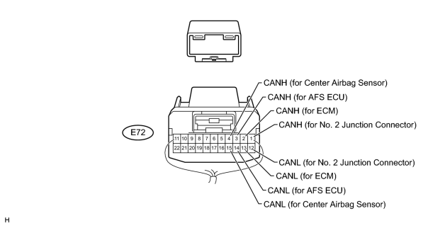
|
No. 1 Junction Connector |
Wiring Color |
Connect to |
|---|---|---|
|
E72-1 (CANH) |
Y |
No. 2 junction connector |
|
E72-12 (CANL) |
B |
|
|
E72-2 (CANH) |
P |
ECM |
|
E72-13 (CANL) |
B |
|
|
E72-3 (CANH) |
LG |
AFS ECU (headlight swivel ECU) |
|
E72-14 (CANL) |
B |
|
|
E72-4 (CANH) |
GR |
Center airbag sensor |
|
E72-15 (CANL) |
B |
(b) NO. 2 JUNCTION CONNECTOR
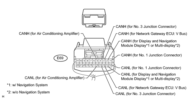
|
No. 2 Junction Connector |
Wiring Color |
Connect to |
|---|---|---|
|
E69-1 (CANH) |
Y |
No. 1 junction connector |
|
E69-12 (CANL) |
B |
|
|
E69-2 (CANH) |
P |
Display and navigation module display*1 Multi-display*2 |
|
E69-13 (CANL) |
B |
|
|
E69-3 (CANH) |
BR |
Network gateway ECU (V bus) |
|
E69-14 (CANL) |
B |
|
|
E69-4 (CANH) |
W |
No. 3 junction connector |
|
E69-15 (CANL) |
B |
|
|
E69-5 (CANH) |
G |
Air conditioning amplifier |
|
E69-16 (CANL) |
B |
*1: w/ Navigation System
*2: w/o Navigation System
(c) NO. 3 JUNCTION CONNECTOR
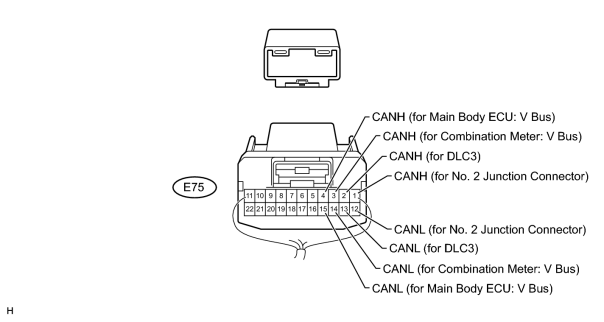
|
No. 3 Junction Connector |
Wiring Color |
Connect to |
|---|---|---|
|
E75-1 (CANH) |
W |
No. 2 junction connector |
|
E75-12 (CANL) |
B |
|
|
E75-2 (CANH) |
G |
DLC3 |
|
E75-13 (CANL) |
B |
|
|
E75-3 (CANH) |
V |
Combination meter (V bus) |
|
E75-14 (CANL) |
B |
|
|
E75-4 (CANH) |
SB |
Main body ECU (cowl side junction block LH) (V bus) |
|
E75-15 (CANL) |
B |
(d) NO. 4 JUNCTION CONNECTOR
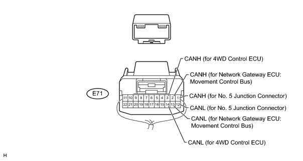
|
No. 4 Junction Connector |
Wiring Color |
Connect to |
|---|---|---|
|
E71-1 (CANH) |
W |
No. 5 junction connector |
|
E71-12 (CANL) |
L |
|
|
E71-2 (CANH) |
SB |
Network gateway ECU (movement control bus) |
|
E71-13 (CANL) |
L |
|
|
E71-3 (CANH) |
P |
4WD control ECU |
|
E71-14 (CANL) |
L |
(e) NO. 5 JUNCTION CONNECTOR
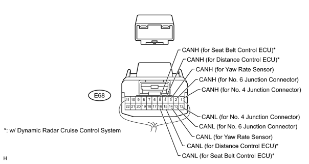
|
No. 5 Junction Connector |
Wiring Color |
Connect to |
|---|---|---|
|
E68-1 (CANH) |
W |
No. 4 junction connector |
|
E68-12 (CANL) |
L |
|
|
E68-2 (CANH) |
Y |
No. 6 junction connector |
|
E68-13 (CANL) |
L |
|
|
E68-3 (CANH) |
BR |
Yaw rate sensor |
|
E68-14 (CANL) |
L |
|
|
E68-4 (CANH)* |
SB |
Distance control ECU |
|
E68-15 (CANL)* |
L |
|
|
E68-5 (CANH)* |
G |
Seat belt control ECU |
|
E68-16 (CANL)* |
L |
*: w/ Dynamic Radar Cruise Control System
(f) NO. 6 JUNCTION CONNECTOR
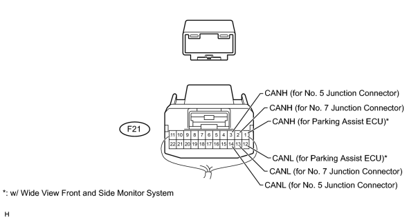
|
No. 6 Junction Connector |
Wiring Color |
Connect to |
|---|---|---|
|
F21-1 (CANH)* |
V |
Parking assist ECU |
|
F21-12 (CANL)* |
L |
|
|
F21-2 (CANH) |
Y |
No. 7 junction connector |
|
F21-13 (CANL) |
L |
|
|
F21-3 (CANH) |
Y |
No. 5 junction connector |
|
F21-14 (CANL) |
L |
*: w/ Wide View Front and Side Monitor System
(g) NO. 7 JUNCTION CONNECTOR
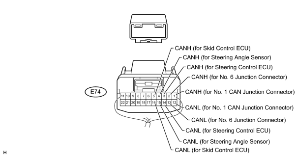
|
No. 7 Junction Connector |
Wiring Color |
Connect to |
|---|---|---|
|
E74-1 (CANH) |
W |
No. 1 CAN junction connector |
|
E74-12 (CANL) |
L |
|
|
E74-2 (CANH) |
Y |
No. 6 junction connector |
|
E74-13 (CANL) |
L |
|
|
E74-3 (CANH) |
LG |
Steering control ECU |
|
E74-14 (CANL) |
L |
|
|
E74-4 (CANH) |
GR |
Steering angle sensor |
|
E74-15 (CANL) |
L |
|
|
E74-5 (CANH) |
V |
Master cylinder solenoid (skid control ECU) |
|
E74-16 (CANL) |
L |
(h) NO. 8 JUNCTION CONNECTOR
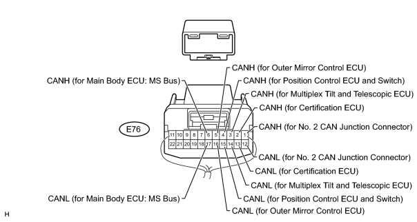
|
No. 8 Junction Connector |
Wiring Color |
Connect to |
|---|---|---|
|
E76-1 (CANH) |
W |
No. 2 CAN junction connector |
|
E76-12 (CANL) |
R |
|
|
E76-2 (CANH) |
LG |
Certification ECU (smart key ECU) |
|
E76-13 (CANL) |
R |
|
|
E76-3 (CANH) |
P |
Multiplex tilt and telescopic ECU |
|
E76-14 (CANL) |
R |
|
|
E76-4 (CANH) |
V |
Position control ECU and switch |
|
E76-15 (CANL) |
R |
|
|
E76-5 (CANH) |
BR |
Outer mirror control ECU |
|
E76-16 (CANL) |
R |
|
|
E76-6 (CANH) |
GR |
Main body ECU (cowl side junction block LH) (MS bus) |
|
E76-17 (CANL) |
R |
(i) NO. 9 JUNCTION CONNECTOR
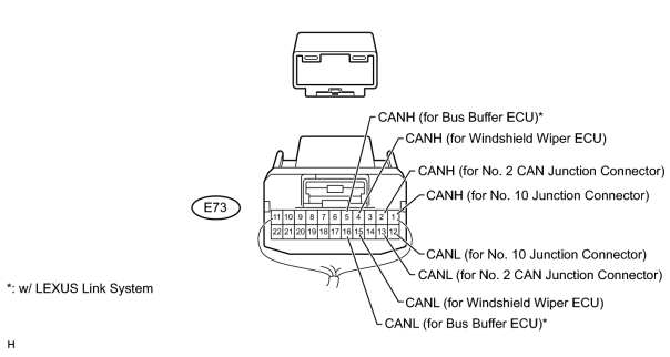
|
No. 9 Junction Connector |
Wiring Color |
Connect to |
|---|---|---|
|
E73-1 (CANH) |
W |
No. 10 junction connector |
|
E73-12 (CANL) |
R |
|
|
E73-2 (CANH) |
Y |
No. 2 CAN junction connector |
|
E73-13 (CANL) |
R |
|
|
E73-4 (CANH) |
LG |
Windshield wiper ECU |
|
E73-15 (CANL) |
R |
|
|
E73-5 (CANH)* |
G |
Bus buffer ECU |
|
E73-16 (CANL)* |
R |
*: w/ LEXUS Link System
(j) NO. 10 JUNCTION CONNECTOR
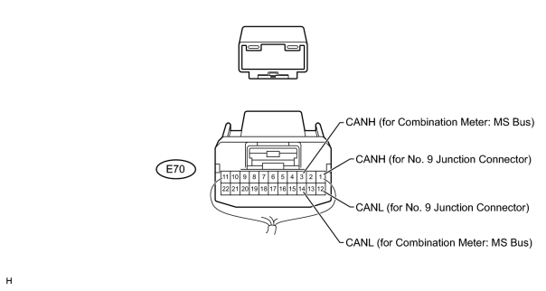
|
No. 10 Junction Connector |
Wiring Color |
Connect to |
|---|---|---|
|
E70-1 (CANH) |
W |
No. 9 Junction Connector |
|
E70-12 (CANL) |
R |
|
|
E70-3 (CANH) |
LG |
Combination Meter (MS bus) |
|
E70-14 (CANL) |
R |
(k) NO. 1 CAN JUNCTION CONNECTOR
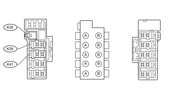
|
Junction Connector A Side |
Wiring Color (CANH Side) |
Wiring Color (CANL Side) |
|---|---|---|
|
Body ground (K28) |
- |
W-B |
|
No. 7 junction connector (K29) |
W |
L |
|
Suspension control ECU (K41) |
V |
L |
(l) NO. 2 CAN JUNCTION CONNECTOR
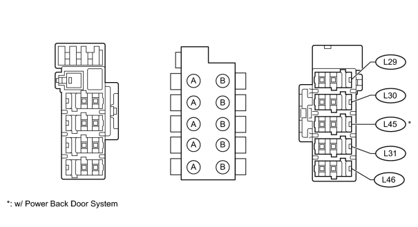
|
Junction Connector B side |
Wiring Color (CANH Side) |
Wiring Color (CANL Side) |
|---|---|---|
|
No. 8 junction connector (L29) |
W |
R |
|
No. 9 junction connector (L30) |
Y |
R |
|
Tire pressure warning ECU (L31) |
G |
R |
|
Power back door ECU (L45)* |
V |
R |
|
No. 2 main body ECU (L46) |
LG |
R |
*: w/ Power Back Door System
|
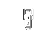
3. TERMINALS OF CONNECTORS FOR JUNCTION CONNECTOR (CAN JUNCTION CONNECTOR)
|
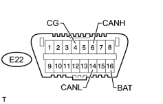
4. CHECK DLC3
(a) Disconnect the cable from the negative (-) battery terminal before measuring the resistances of the main wire and the branch wire.
NOTICE:
When disconnecting the cable, some systems need to be initialized after the cable is reconnected
 .
.
|
(b) Measure the resistance according to the value(s) in the table below.
|
5. CHECK MASTER CYLINDER SOLENOID (SKID CONTROL ECU)
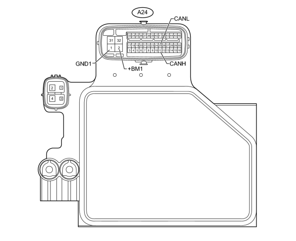
(a) Disconnect the A24 ECU connector.
(b) Measure the resistance according to the value(s) in the table below.
|
Terminal No. (Symbol) |
Wiring Color |
Switch Condition |
Specified Condition |
|---|---|---|---|
|
A24-11 (CANH) - A24-25 (CANL) |
V - L |
Engine switch off |
54 to 69 Ω |
|
A24-11 (CANH) - A24-1 (GND1) |
V - W-B |
Engine switch off |
200 Ω or higher |
|
A24-25 (CANL) - A24-1 (GND1) |
L - W-B |
Engine switch off |
200 Ω or higher |
|
A24-11 (CANH) - A24-2 (+BM1) |
V - B |
Engine switch off |
6 kΩ or higher |
|
A24-25 (CANL) - A24-2 (+BM1) |
L - B |
Engine switch off |
6 kΩ or higher |
6. CHECK AIR CONDITIONING AMPLIFIER
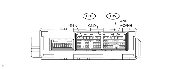
(a) Disconnect the E35 and E36 amplifier connectors.
(b) Measure the voltage and resistance according to the value(s) in the table below.
|
Terminal No. (Symbol) |
Wiring Color |
Condition |
Specified Condition |
|---|---|---|---|
|
E35-3 (CANH) - E35-4 (CANL) |
G - B |
Engine switch off |
54 to 69 Ω |
|
E35-3 (CANH) - E36-1 (GND) |
G - W-B |
Engine switch off |
200 Ω or higher |
|
E35-4 (CANL) - E36-1 (GND) |
B - W-B |
Engine switch off |
200 Ω or higher |
|
E35-3 (CANH) - E36-6 (+B1) |
G - R |
Engine switch off |
6 kΩ or higher |
|
E35-4 (CANL) - E36-6 (+B1) |
B - R |
Engine switch off |
6 kΩ or higher |
7. CHECK ECM
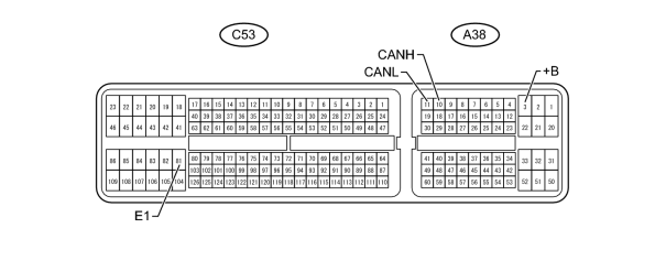
(a) Disconnect the A38 and C53 ECM connectors.
(b) Measure the resistance according to the value(s) in the table below.
|
Terminal No. (Symbol) |
Wiring Color |
Switch Condition |
Specified Condition |
|---|---|---|---|
|
A38-10 (CANH) - A38-11 (CANL) |
P - B |
Engine switch off |
108 to 132 Ω |
|
A38-10 (CANH) - C53-81 (E1) |
P - W-B |
Engine switch off |
200 Ω or higher |
|
A38-11 (CANL) - C53-81 (E1) |
B - W-B |
Engine switch off |
200 Ω or higher |
|
A38-10 (CANH) - A38-3 (+B) |
P - B |
Engine switch off |
6 kΩ or higher |
|
A38-11 (CANL) - A38-3 (+B) |
B - B |
Engine switch off |
6 kΩ or higher |
8. CHECK MAIN BODY ECU (COWL SIDE JUNCTION BLOCK LH)
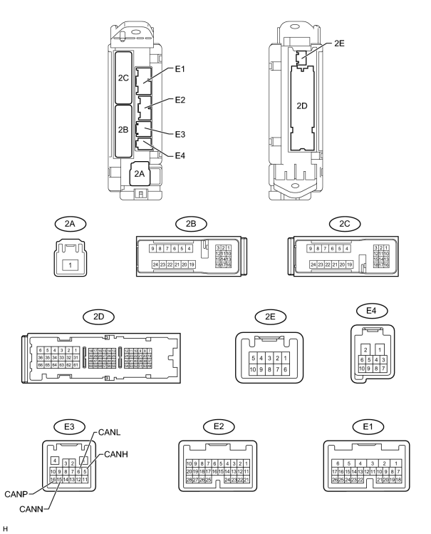
(a) Disconnect the E3 ECU connector.
(b) Disconnect the 2A and 2D junction connectors.
(c) Measure the resistance according to the value(s) in the table below.
|
Terminal No. (Symbol) |
Wiring Color |
Switch Condition |
Specified Condition |
|---|---|---|---|
|
E3-5 (CANH) - E3-6 (CANL)*1 |
SB - B |
Engine switch off |
54 to 69 Ω |
|
E3-5 (CANH) - 2D-62 (GND2)*1 |
SB - W-B |
Engine switch off |
200 Ω or higher |
|
E3-6 (CANL) - 2D-62 (GND2)*1 |
B - W-B |
Engine switch off |
200 Ω or higher |
|
E3-5 (CANH) - 2A-1 (ALTB)*1 |
SB - B |
Engine switch off |
6 kΩ or higher |
|
E3-6 (CANL) - 2A-1 (ALTB)*1 |
B - B |
Engine switch off |
6 kΩ or higher |
|
E3-16 (CANP) - E3-15 (CANN)*2 |
GR - R |
Engine switch off |
108 to 132 Ω |
|
E3-16 (CANP) - 2D-62 (GND2)*2 |
GR - W-B |
Engine switch off |
200 Ω or higher |
|
E3-15 (CANN) - 2D-62 (GND2)*2 |
R - W-B |
Engine switch off |
200 Ω or higher |
|
E3-16 (CANP) - 2A-1 (ALTB)*2 |
GR - B |
Engine switch off |
6 kΩ or higher |
|
E3-15 (CANN) - 2A-1 (ALTB)*2 |
R - B |
Engine switch off |
6 kΩ or higher |
*1: For V bus
*2: For MS bus
9. CHECK COMBINATION METER
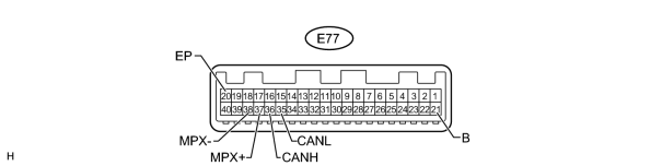
(a) Disconnect the E77 meter connector.
(b) Measure the resistance according to the value(s) in the table below.
|
Terminal No. (Symbol) |
Wiring Color |
Switch Condition |
Specified Condition |
|---|---|---|---|
|
E77-36 (CANH) - E77-35 (CANL)*1 |
V - B |
Engine switch off |
108 to 132 Ω |
|
E77-36 (CANH) - E77-20 (EP)*1 |
V - W-B |
Engine switch off |
200 Ω or higher |
|
E77-35 (CANL) - E77-20 (EP)*1 |
B - W-B |
Engine switch off |
200 Ω or higher |
|
E77-36 (CANH) - E77-21 (B)*1 |
V - R |
Engine switch off |
6 kΩ or higher |
|
E77-35 (CANL) - E77-21 (B)*1 |
B - R |
Engine switch off |
6 kΩ or higher |
|
E77-37 (MPX+) - E77-38 (MPX-)*2 |
LG - R |
Engine switch off |
108 to 132 Ω |
|
E77-37 (MPX+) - E77-20 (EP)*2 |
LG - W-B |
Engine switch off |
200 Ω or higher |
|
E77-38 (MPX-) - E77-20 (EP)*2 |
R - W-B |
Engine switch off |
200 Ω or higher |
|
E77-37 (MPX+) - E77-21 (B)*2 |
LG - R |
Engine switch off |
6 kΩ or higher |
|
E77-38 (MPX-) - E77-21 (B)*2 |
R - R |
Engine switch off |
6 kΩ or higher |
*1: For V bus
*2: For MS bus
10. CHECK CENTER AIRBAG SENSOR
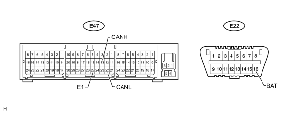
(a) Disconnect the E47 sensor connector.
(b) Measure the resistance according to the value(s) in the table below.
|
Terminal No. (Symbol) |
Wiring Color |
Switch Condition |
Specified Condition |
|---|---|---|---|
|
E47-13 (CANH) - E47-22 (CANL) |
GR - B |
Engine switch off |
54 to 69 Ω |
|
E47-13 (CANH) - E47-25 (E1) |
GR - W-B |
Engine switch off |
200 Ω or higher |
|
E47-22 (CANL) - E47-25 (E1) |
B - W-B |
Engine switch off |
200 Ω or higher |
|
E47-13 (CANH) - E22-16 (BAT) |
GR - O |
Engine switch off |
6 kΩ or higher |
|
E47-22 (CANL) - E22-16 (BAT) |
B - O |
Engine switch off |
6 kΩ or higher |
11. CHECK DISPLAY AND NAVIGATION MODULE DISPLAY
For vehicles with the navigation system only.
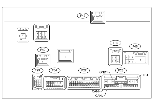
(a) Disconnect the F28 display connector.
(b) Measure the resistance according to the value(s) in the table below.
|
Terminal No. (Symbol) |
Wiring Color |
Switch Condition |
Specified Condition |
|---|---|---|---|
|
F28-26 (CANH) - F28-25 (CANL) |
P - B |
Engine switch off |
54 to 69 Ω |
|
F28-26 (CANH) - F28-10 (GND1) |
P - W-B |
Engine switch off |
200 Ω or higher |
|
F28-25 (CANL) - F28-10 (GND1) |
B - W-B |
Engine switch off |
200 Ω or higher |
|
F28-26 (CANH) - F28-1 (+B1) |
P - R |
Engine switch off |
6 kΩ or higher |
|
F28-25 (CANL) - F28-1 (+B1) |
B - R |
Engine switch off |
6 kΩ or higher |
12. CHECK MULTI-DISPLAY
For vehicles without the navigation system only.
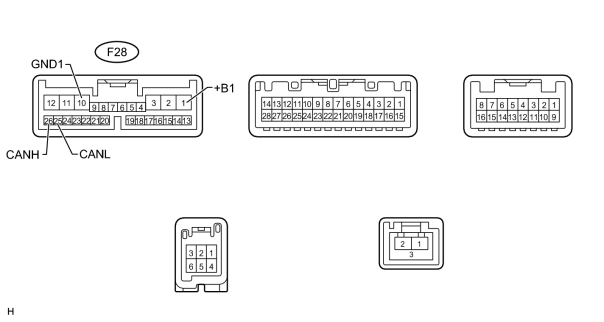
(a) Disconnect the F28 multi-display connector.
(b) Measure the resistance according to the value(s) in the table below.
|
Terminal No. (Symbol) |
Wiring Color |
Switch Condition |
Specified Condition |
|---|---|---|---|
|
F28-26 (CANH) - F28-25 (CANL) |
P - B |
Engine switch off |
54 to 69 Ω |
|
F28-26 (CANH) - F28-10 (GND1) |
P - W-B |
Engine switch off |
200 Ω or higher |
|
F28-25 (CANL) - F28-10 (GND1) |
B - W-B |
Engine switch off |
200 Ω or higher |
|
F28-26 (CANH) - F28-1 (+B1) |
P - R |
Engine switch off |
6 kΩ or higher |
|
F28-25 (CANL) - F28-1 (+B1) |
B - R |
Engine switch off |
6 kΩ or higher |
13. CHECK STEERING ANGLE SENSOR
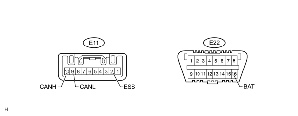
(a) Disconnect the E11 sensor connector.
(b) Measure the resistance according to the value(s) in the table below.
|
Terminal No. (Symbol) |
Wiring Color |
Switch Condition |
Specified Condition |
|---|---|---|---|
|
E11-10 (CANH) - E11-9 (CANL) |
GR - L |
Engine switch off |
54 to 69 Ω |
|
E11-10 (CANH) - E11-2 (ESS) |
GR - W-B |
Engine switch off |
200 Ω or higher |
|
E11-9 (CANL) - E11-2 (ESS) |
L - W-B |
Engine switch off |
200 Ω or higher |
|
E11-10 (CANH) - E22-16 (BAT) |
GR - O |
Engine switch off |
6 kΩ or higher |
|
E11-9 (CANL) - E22-16 (BAT) |
L - O |
Engine switch off |
6 kΩ or higher |
14. CHECK YAW RATE SENSOR
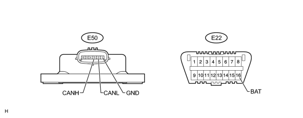
(a) Disconnect the E50 sensor connector.
(b) Measure the resistance according to the value(s) in the table below.
|
Terminal No. (Symbol) |
Wiring Color |
Switch Condition |
Specified Condition |
|---|---|---|---|
|
E50-3 (CANH) - E50-2 (CANL) |
BR - L |
Engine switch off |
54 to 69 Ω |
|
E50-3 (CANH) - E50-1 (GND) |
BR - W-B |
Engine switch off |
200 Ω or higher |
|
E50-2 (CANL) - E50-1 (GND) |
L - W-B |
Engine switch off |
200 Ω or higher |
|
E50-3 (CANH) - E22-16 (BAT) |
BR - O |
Engine switch off |
6 kΩ or higher |
|
E50-2 (CANL) - E22-16 (BAT) |
L - O |
Engine switch off |
6 kΩ or higher |
15. CHECK SEAT BELT CONTROL ECU
For vehicles with the dynamic radar cruise control system only.
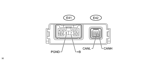
(a) Disconnect the E41 and E42 ECU connectors.
(b) Measure the resistance according to the value(s) in the table below.
|
Terminal No. (Symbol) |
Wiring Color |
Switch Condition |
Specified Condition |
|---|---|---|---|
|
E42-1 (CANH) - E42-2 (CANL) |
G - L |
Engine switch off |
54 to 69 Ω |
|
E42-1 (CANH) - E41-8 (PGND) |
G - W-B |
Engine switch off |
200 Ω or higher |
|
E42-2 (CANL) - E41-8 (PGND) |
L - W-B |
Engine switch off |
200 Ω or higher |
|
E42-1 (CANH) - E41-7 (+B) |
G - R |
Engine switch off |
6 kΩ or higher |
|
E42-2 (CANL) - E41-7 (+B) |
L - R |
Engine switch off |
6 kΩ or higher |
16. CHECK OUTER MIRROR CONTROL ECU
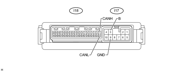
(a) Disconnect the I18 and I17 ECU connectors.
(b) Measure the resistance according to the value(s) in the table below.
|
Terminal No. (Symbol) |
Wiring Color |
Switch Condition |
Specified Condition |
|---|---|---|---|
|
I18-1 (CANH) - I18-21 (CANL) |
BR - R |
Engine switch off |
54 to 69 Ω |
|
I18-1 (CANH) - I17-9 (GND) |
BR - W-B |
Engine switch off |
200 Ω or higher |
|
I18-21 (CANL) - I17-9 (GND) |
R - W-B |
Engine switch off |
200 Ω or higher |
|
I18-1 (CANH) - I17-3 (B) |
BR - R |
Engine switch off |
6 kΩ or higher |
|
I18-21 (CANL) - I17-3 (B) |
R - R |
Engine switch off |
6 kΩ or higher |
17. CHECK MULTIPLEX TILT AND TELESCOPIC ECU
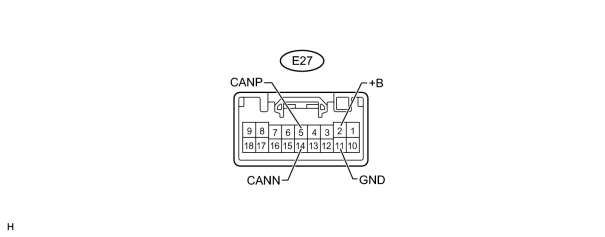
(a) Disconnect the E27 ECU connector.
(b) Measure the resistance according to the value(s) in the table below.
|
Terminal No. (Symbol) |
Wiring Color |
Switch Condition |
Specified Condition |
|---|---|---|---|
|
E27-5 (CANP) - E27-14 (CANN) |
P - R |
Engine switch off |
54 to 69 Ω |
|
E27-5 (CANP) - E27-11 (GND) |
P - W-B |
Engine switch off |
200 Ω or higher |
|
E27-14 (CANN) - E27-11 (GND) |
R - W-B |
Engine switch off |
200 Ω or higher |
|
E27-5 (CANP) - E27-2 (+B) |
P - L |
Engine switch off |
6 kΩ or higher |
|
E27-14 (CANN) - E27-2 (+B) |
R - L |
Engine switch off |
6 kΩ or higher |
18. CHECK CERTIFICATION ECU (SMART KEY ECU)
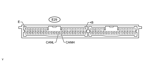
(a) Disconnect the E29 ECU connector.
(b) Measure the resistance according to the value(s) in the table below.
|
Terminal No. (Symbol) |
Wiring Color |
Switch Condition |
Specified Condition |
|---|---|---|---|
|
E29-27 (CANH) - E29-28 (CANL) |
LG - R |
Engine switch off |
54 to 69 Ω |
|
E29-27 (CANH) - E29-17 (E) |
LG - W-B |
Engine switch off |
200 Ω or higher |
|
E29-28 (CANL) - E29-17 (E) |
R - W-B |
Engine switch off |
200 Ω or higher |
|
E29-27 (CANH) - E29-1 (+B) |
LG - B |
Engine switch off |
6 kΩ or higher |
|
E29-28 (CANL) - E29-1 (+B) |
R - B |
Engine switch off |
6 kΩ or higher |
19. CHECK POSITION CONTROL ECU AND SWITCH
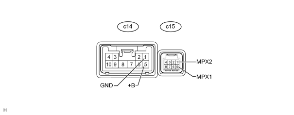
(a) Disconnect the c14 and c15 ECU connectors.
(b) Measure the resistance according to the value(s) in the table below.
|
Terminal No. (Symbol) |
Wiring Color |
Switch Condition |
Specified Condition |
|---|---|---|---|
|
c15-5 (MPX1) - c15-1 (MPX2) |
V - R |
Engine switch off |
54 to 69 Ω |
|
c15-5 (MPX1) - c14-1 (GND) |
V - W-B |
Engine switch off |
200 Ω or higher |
|
c15-1 (MPX2) - c14-1 (GND) |
R - W-B |
Engine switch off |
200 Ω or higher |
|
c15-5 (MPX1) - c14-5 (+B) |
V - L |
Engine switch off |
6 kΩ or higher |
|
c15-1 (MPX2) - c14-5 (+B) |
R - L |
Engine switch off |
6 kΩ or higher |
20. CHECK TIRE PRESSURE WARNING ECU
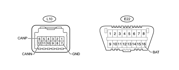
(a) Disconnect the L10 connector.
(b) Measure the resistance according to the value(s) in the table below.
|
Terminal No. (Symbol) |
Wiring Color |
Switch Condition |
Specified Condition |
|---|---|---|---|
|
L10-6 (CANP) - L10-12 (CANN) |
G - R |
Engine switch off |
54 to 69 Ω |
|
L10-6 (CANP) - L10-7 (GND) |
G - W-B |
Engine switch off |
200 Ω or higher |
|
L10-12 (CANN) - L10-7 (GND) |
R - W-B |
Engine switch off |
200 Ω or higher |
|
L10-6 (CANP) - E22-16 (BAT) |
G - O |
Engine switch off |
6 kΩ or higher |
|
L10-12 (CANN) - E22-16 (BAT) |
R - O |
Engine switch off |
6 kΩ or higher |
21. CHECK 4WD CONTROL ECU
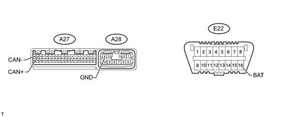
(a) Disconnect the A27 and A28 ECU connectors.
(b) Measure the resistance according to the value(s) in the table below.
|
Terminal No. (Symbol) |
Wiring Color |
Switch Condition |
Specified Condition |
|---|---|---|---|
|
A27-19 (CAN+) - A27-20 (CAN-) |
P - L |
Engine switch off |
54 to 69 Ω |
|
A27-19 (CAN+) - A28-4 (GND) |
P - W |
Engine switch off |
200 Ω or higher |
|
A27-20 (CAN-) - A28-4 (GND) |
L - W |
Engine switch off |
200 Ω or higher |
|
A27-19 (CAN+) - E22-16 (BAT) |
P - O |
Engine switch off |
6 kΩ or higher |
|
A27-20 (CAN-) - E22-16 (BAT) |
L - O |
Engine switch off |
6 kΩ or higher |
22. CHECK NETWORK GATEWAY ECU

(a) Disconnect the E31 ECU connector.
(b) Measure the resistance according to the value(s) in the table below.
|
Terminal No. (Symbol) |
Wiring Color |
Switch Condition |
Specified Condition |
|---|---|---|---|
|
E31-16 (CA1H) - E31-15 (CA1L)*1 |
BR - B |
Engine switch off |
54 to 69 Ω |
|
E31-16 (CA1H) - E31-4 (GND)*1 |
BR - W-B |
Engine switch off |
200 Ω or higher |
|
E31-15 (CA1L) - E31-4 (GND)*1 |
B - W-B |
Engine switch off |
200 Ω or higher |
|
E31-16 (CA1H) - E31-2 (BATT)*1 |
BR - R |
Engine switch off |
6 kΩ or higher |
|
E31-15 (CA1L) - E31-2 (BATT)*1 |
B - R |
Engine switch off |
6 kΩ or higher |
|
E31-13 (CA2H) - E31-12 (CA2L)*2 |
SB - L |
Engine switch off |
108 to 132 Ω |
|
E31-13 (CA2H) - E31-4 (GND)*2 |
SB - W-B |
Engine switch off |
200 Ω or higher |
|
E31-12 (CA2L) - E31-4 (GND)*2 |
L - W-B |
Engine switch off |
200 Ω or higher |
|
E31-13 (CA2H) - E31-2 (BATT)*2 |
SB - R |
Engine switch off |
6 kΩ or higher |
|
E31-12 (CA2L) - E31-2 (BATT)*2 |
L - R |
Engine switch off |
6 kΩ or higher |
*1: For V bus
*2: For movement control bus
23. CHECK STEERING CONTROL ECU
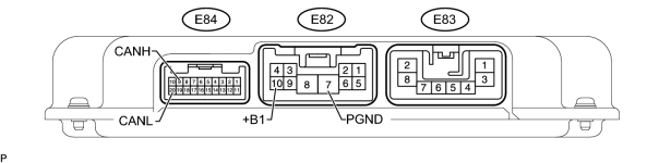
(a) Disconnect the E82 and E84 ECU connectors.
(b) Measure the resistance according to the value(s) in the table below.
|
Terminal No. (Symbol) |
Wiring Color |
Switch Condition |
Specified Condition |
|---|---|---|---|
|
E84-9 (CANH) - E84-20 (CANL) |
LG - L |
Engine switch off |
200 Ω or higher |
|
E84-9 (CANH) - E82-7 (PGND) |
LG - W-B |
Engine switch off |
200 Ω or higher |
|
E84-20 (CANL) - E82-7 (PGND) |
L - W-B |
Engine switch off |
200 Ω or higher |
|
E84-9 (CANH) - E82-10 (+B1) |
LG - R |
Engine switch off |
6 kΩ or higher |
|
E84-20 (CANL) - E82-10 (+B1) |
L - R |
Engine switch off |
6 kΩ or higher |
24. CHECK SUSPENSION CONTROL ECU
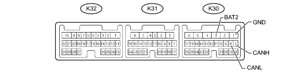
(a) Disconnect the K30 ECU connector.
(b) Measure the resistance according to the value(s) in the table below.
|
Terminal No. (Symbol) |
Wiring Color |
Switch Condition |
Specified Condition |
|---|---|---|---|
|
K30-7 (CANH) - K30-8 (CANL) |
V - L |
Engine switch off |
54 to 69 Ω |
|
K30-7 (CANH) - K30-1 (GND) |
V - W-B |
Engine switch off |
200 Ω or higher |
|
K30-8 (CANL) - K30-1 (GND) |
L - W-B |
Engine switch off |
200 Ω or higher |
|
K30-7 (CANH) - K30-3 (BAT2) |
V - R |
Engine switch off |
6 kΩ or higher |
|
K30-8 (CANL) - K30-3 (BAT2) |
L - R |
Engine switch off |
6 kΩ or higher |
25. CHECK WINDSHIELD WIPER ECU
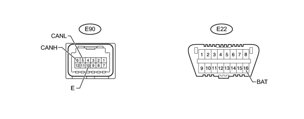
(a) Disconnect the E90 ECU connector.
(b) Measure the resistance according to the value(s) in the table below.
|
Terminal No. (Symbol) |
Wiring Color |
Switch Condition |
Specified Condition |
|---|---|---|---|
|
E90-6 (CANH) - E90-5 (CANL) |
LG - R |
Engine switch off |
54 to 69 Ω |
|
E90-6 (CANH) - E90-10 (E) |
LG - W-B |
Engine switch off |
200 Ω or higher |
|
E90-5 (CANL) - E90-10 (E) |
R - W-B |
Engine switch off |
200 Ω or higher |
|
E90-6 (CANH) - E22-16 (BAT) |
LG - O |
Engine switch off |
6 kΩ or higher |
|
E90-5 (CANL) - E22-16 (BAT) |
R - O |
Engine switch off |
6 kΩ or higher |
26. CHECK PARKING ASSIST ECU
For vehicles with the wide view front and side monitor system only.
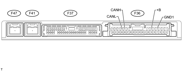
(a) Disconnect the F36 ECU connector.
(b) Measure the resistance according to the value(s) in the table below.
|
Terminal No. (Symbol) |
Wiring Color |
Switch Condition |
Specified Condition |
|---|---|---|---|
|
F36-9 (CANH) - F36-10 (CANL) |
V - L |
Engine switch off |
54 to 69 Ω |
|
F36-9 (CANH) - F36-4 (GND1) |
V - W-B |
Engine switch off |
200 Ω or higher |
|
F36-10 (CANL) - F36-4 (GND1) |
L - W-B |
Engine switch off |
200 Ω or higher |
|
F36-9 (CANH) - F36-6 (+B) |
V - L |
Engine switch off |
6 kΩ or higher |
|
F36-10 (CANL) - F36-6 (+B) |
L - L |
Engine switch off |
6 kΩ or higher |
27. CHECK DISTANCE CONTROL ECU
For vehicles with the dynamic radar cruise control system only.

(a) Disconnect the E86 ECU connector.
(b) Measure the resistance according to the value(s) in the table below.
|
Terminal No. (Symbol) |
Wiring Color |
Switch Condition |
Specified Condition |
|---|---|---|---|
|
E86-8 (CANH) - E86-9 (CANL) |
SB - L |
Engine switch off |
54 to 69 Ω |
|
E86-8 (CANH) - E86-12 (GND) |
SB - BR |
Engine switch off |
200 Ω or higher |
|
E86-9 (CANL) - E86-12 (GND) |
L - BR |
Engine switch off |
200 Ω or higher |
|
E86-8 (CANH) - E86-1 (B) |
SB - R |
Engine switch off |
6 kΩ or higher |
|
E86-9 (CANL) - E86-1 (B) |
L - R |
Engine switch off |
6 kΩ or higher |
28. CHECK POWER BACK DOOR UNIT (POWER BACK DOOR ECU)
For vehicles with the power back door system only.

(a) Disconnect the L36 unit connector.
(b) Measure the resistance according to the value(s) in the table below.
|
Terminal No. (Symbol) |
Wiring Color |
Switch Condition |
Specified Condition |
|---|---|---|---|
|
L36-6 (MPX1) - L36-5 (MPX2) |
V - R |
Engine switch off |
54 to 69 Ω |
|
L36-6 (MPX1) - L36-11 (GND) |
V - W-B |
Engine switch off |
200 Ω or higher |
|
L36-5 (MPX2) - L36-11 (GND) |
R - W-B |
Engine switch off |
200 Ω or higher |
|
L36-6 (MPX1) - L36-10 (ECUB) |
V - R |
Engine switch off |
6 kΩ or higher |
|
L36-5 (MPX2) - L36-10 (ECUB) |
R - R |
Engine switch off |
6 kΩ or higher |
29. CHECK AFS ECU (HEADLIGHT SWIVEL ECU)
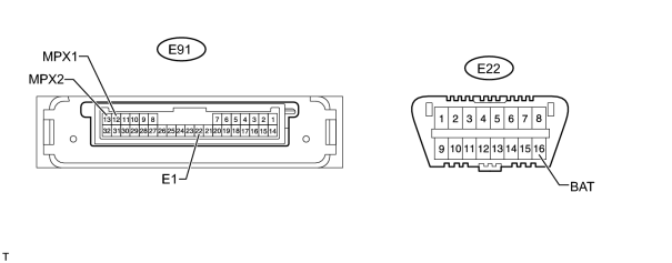
(a) Disconnect the E91 ECU connector.
(b) Measure the resistance according to the value(s) in the table below.
|
Terminal No. (Symbol) |
Wiring Color |
Switch Condition |
Specified Condition |
|---|---|---|---|
|
E91-12 (MPX1) - E91-13 (MPX2) |
LG - B |
Engine switch off |
54 to 69 Ω |
|
E91-12 (MPX1) - E91-22 (E1) |
LG - W-B |
Engine switch off |
200 Ω or higher |
|
E91-13 (MPX2) - E91-22 (E1) |
B - W-B |
Engine switch off |
200 Ω or higher |
|
E91-12 (MPX1) - E22-16 (BAT) |
LG - O |
Engine switch off |
6 kΩ or higher |
|
E91-13 (MPX2) - E22-16 (BAT) |
B - O |
Engine switch off |
6 kΩ or higher |
30. CHECK NO. 2 MAIN BODY ECU
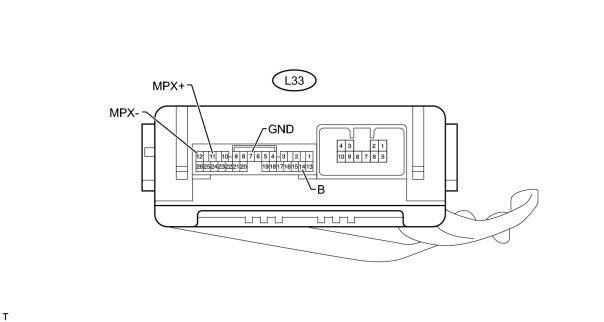
(a) Disconnect the L33 ECU connector.
(b) Measure the resistance according to the value(s) in the table below.
|
Terminal No. (Symbol) |
Wiring Color |
Switch Condition |
Specified Condition |
|---|---|---|---|
|
L33-11 (MPX+) - L33-12 (MPX-) |
LG - R |
Engine switch off |
54 to 69 Ω |
|
L33-11 (MPX+) - L33-7 (GND) |
LG - W-B |
Engine switch off |
200 Ω or higher |
|
L33-12 (MPX-) - L33-7 (GND) |
R - W-B |
Engine switch off |
200 Ω or higher |
|
L33-11 (MPX+) - L33-14 (BECU) |
LG - R |
Engine switch off |
6 kΩ or higher |
|
L33-12 (MPX-) - L33-14 (BECU) |
R - R |
Engine switch off |
6 kΩ or higher |

|

|