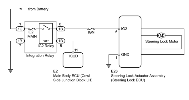
- Steering lock actuator assembly (steering lock ECU)
- IGN fuse
- IG2 MAIN fuse
- Integration relay (IG2 relay)
- Main body ECU
- Harness or connector
| Last Modified: 11-27-2007 | 1.6 C | |
| Service Category: Steering | Section: Steering Column | |
| Model Year: 2008 | Model: LX570 | Doc ID: RM000001T1K00BX |
| Title: STEERING COLUMN: STEERING LOCK SYSTEM: DESCRIPTION (2008 LX570) | ||
|
DTC |
B2788 |
IG2 Signal Malfunction |
DESCRIPTION
The steering lock ECU determines the on/off status of the engine switch through the IG2 signal circuit.
After receiving an integration relay (IG2 relay) on signal, the steering lock ECU determines that the vehicle is moving.
The steering lock ECU does not lock the steering when it receives the integration relay (IG2 relay) on signal. This prevents the steering from being locked while the vehicle is moving.
The diagnosis information of the steering lock ECU is transmitted to the Techstream via the certification ECU (smart key ECU assembly) as the steering lock ECU is not connected to the CAN communication system.
|
DTC Code |
Detection Condition |
Trouble Area |
|---|---|---|
|
B2788 |
An open or short in the IG2 signal circuit. |
|
WIRING DIAGRAM
INSPECTION PROCEDURE
HINT:
When the engine switch is off, the main body ECU may occasionally go into a non-active state called sleep mode. Therefore, before proceeding with the inspection, it is necessary to perform the following steps to wake up the ECU:
With the engine switch off, open the driver door. Then (with the engine switch still off) open and close any door several times at 1.5 second intervals.
PROCEDURE
|
1. |
INSPECT STEERING LOCK ECU |
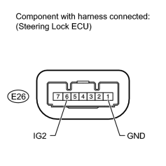
(a) Measure the voltage according to the value(s) in the table below.
Standard Voltage:
|
Tester Connection |
Switch Condition |
Specified Condition |
|---|---|---|
|
E26-6 (IG2) - E26-1 (GND) |
Engine switch off |
Below 1 V |
|
E26-6 (IG2) - E26-1 (GND) |
Engine switch on (IG) |
11 to 14 V |
|

|
3. |
INSPECT FUSE (IGN, IG2 MAIN) |
(a) Remove the IGN and IG2 MAIN fuses from the engine room relay block.
(b) Measure the resistance according to the value(s) in the table below.
Standard Resistance:
|
Tester Connection |
Condition |
Specified Condition |
|---|---|---|
|
IGN fuse |
Always |
Below 1 Ω |
|
IG2 MAIN fuse |
Always |
Below 1 Ω |
|
|
4. |
INSPECT INTEGRATION RELAY (IG2 RELAY) |
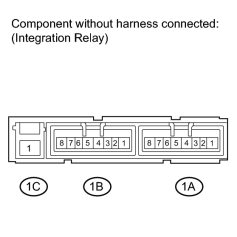
(a) Remove the integration relay from the engine room relay block.
(b) Measure the resistance according to the value(s) in the table below.
Standard Resistance:
|
Tester Connection |
Condition |
Specified Condition |
|---|---|---|
|
1B-8 - 1C-1 |
Battery voltage applied to terminals 1B-6 and 1B-7 |
Below 1 Ω |
|
1B-8 - 1C-1 |
Battery voltage not applied to terminals 1B-6 and 1B-7 |
10 kΩ or higher |
|
|
5. |
CHECK HARNESS AND CONNECTOR (STEERING LOCK ECU - INTEGRATION RELAY (IG2 RELAY) AND BODY GROUND) |
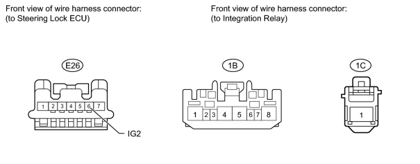
(a) Disconnect the E26 steering lock ECU connector.
(b) Disconnect the 1B and 1C integration relay connectors.
(c) Measure the voltage and resistance according to the value(s) in the table below.
Standard Voltage:
|
Tester Connection |
Condition |
Specified Condition |
|---|---|---|
|
1C-1 - Body ground |
Always |
11 to 14 V |
Standard Resistance:
|
Tester Connection |
Condition |
Specified Condition |
|---|---|---|
|
E26-6 (IG2) - 1B-8 |
Always |
Below 1 Ω |
|
E26-6 (IG2) or 1B-8 - Body ground |
Always |
10 kΩ or higher |
|
|
6. |
CHECK HARNESS AND CONNECTOR (MAIN BODY ECU - INTEGRATION RELAY (IG2 RELAY) AND BODY GROUND) |
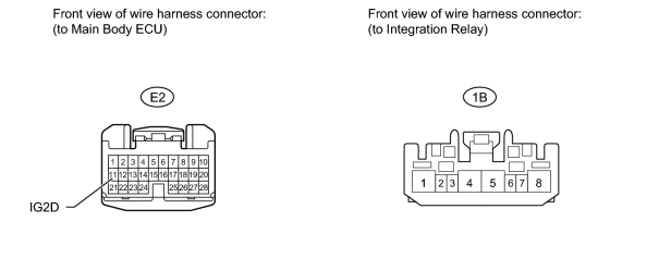
(a) Disconnect the E2 main body ECU connector.
(b) Disconnect the 1B integration relay connector.
(c) Measure the resistance according to the value(s) in the table below.
Standard Resistance:
|
Tester Connection |
Condition |
Specified Condition |
|---|---|---|
|
E2-11 (IG2D) - 1B-6 |
Always |
Below 1 Ω |
|
1B-7 - Body ground |
Always |
Below 1 Ω |
|
E2-11 (IG2D) or 1B-6 - Body ground |
Always |
10 kΩ or higher |
|

|

|