- "Combination Meter" is not displayed on "CAN Bus Check".
| Last Modified: 11-27-2007 | 1.6 J | |
| Service Category: Power Source/Network | Section: Networking | |
| Model Year: 2008 | Model: LX570 | Doc ID: RM000001TNA00JX |
| Title: NETWORKING: CAN COMMUNICATION SYSTEM: DESCRIPTION (2008 LX570) | ||
|
Combination Meter ECU Communication Stop Mode |
DESCRIPTION
|
Detection Item |
Symptom |
Trouble Area |
|---|---|---|
|
Combination Meter ECU Communication Stop Mode |
When either condition below is met:
|
|
WIRING DIAGRAM
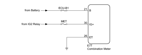
INSPECTION PROCEDURE
HINT:
Operating the engine switch, any switches or any doors triggers related ECU and sensor communication with the CAN, which causes resistance variation.
PROCEDURE
|
1. |
CHECK HARNESS AND CONNECTOR (COMBINATION METER - BATTERY AND BODY GROUND) |
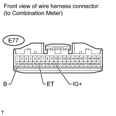
|
(a) Disconnect the E77 combination meter connector. |
(b) Measure the resistance according to the value(s) in the table below.
Standard Resistance:
|
Tester Connection |
Condition |
Specified Condition |
|---|---|---|
|
E77-26 (ET) - Body ground |
Always |
Below 1 Ω |
(c) Measure the voltage according to the value(s) in the table below.
Standard Voltage:
|
Tester Connection |
Switch Condition |
Specified Condition |
|---|---|---|
|
E77-21 (B) - Body ground |
Always |
11 to 14 V |
|
E77-30 (IG+) - Body ground |
Engine switch on (IG) |
11 to 14 V |
|


|

|