- Harness or connector
- Rear television camera
- Multi-display assembly
| Last Modified: 11-27-2007 | 1.6 C | |
| Service Category: Audio/Visual/Telematics | Section: Audio/Video | |
| Model Year: 2008 | Model: LX570 | Doc ID: RM000001WU102DX |
| Title: AUDIO / VIDEO: AUDIO AND VISUAL SYSTEM: DESCRIPTION (2008 LX570) | ||
|
DTC |
5C-40 |
Camera Picture Error |
DESCRIPTION
HINT:
If the vehicle has a navigation system, "multi-display" refers to the "display and navigation module display".
|
DTC Code |
DTC Detection Condition |
Trouble Area |
|---|---|---|
|
5C-40 |
A synchronous signal from the camera cannot be transmitted. |
|
WIRING DIAGRAM
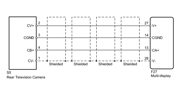
INSPECTION PROCEDURE
HINT:
After the inspection is completed, clear the DTCs
 .
.
PROCEDURE
|
1. |
CHECK HARNESS AND CONNECTOR (MULTI-DISPLAY - REAR TELEVISION CAMERA) |
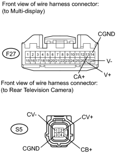
(a) Disconnect the F27 display connector.
(b) Disconnect the S5 camera connector.
(c) Measure the resistance according to the value(s) in the table below.
Standard Resistance:
|
Tester Connection |
Condition |
Specified Condition |
|---|---|---|
|
S5-4 (CB+) - F27-13 (CA+) |
Always |
Below 1 Ω |
|
S5-3 (CGND) - F27-14 (CGND) |
Always |
Below 1 Ω |
|
S5-2 (CV+) - F27-27 (V+) |
Always |
Below 1 Ω |
|
S5-1 (CV-) - F27-28 (V-) |
Always |
Below 1 Ω |
|
S5-4 (CB+) - Body ground |
Always |
10 kΩ or higher |
|
S5-3 (CGND) - Body ground |
Always |
10 kΩ or higher |
|
S5-2 (CV+) - Body ground |
Always |
10 kΩ or higher |
|
S5-1 (CV-) - Body ground |
Always |
10 kΩ or higher |
|

|
2. |
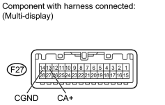
CHECK MULTI-DISPLAY (CA+ VOLTAGE) |
|
(a) Measure the voltage according to the value(s) in the table below. Standard Voltage:
|
|

|

|