- One side of CAN branch wire is open
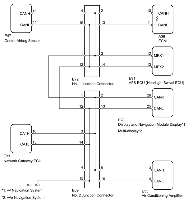
- Display and navigation module display*1
- Multi-display*2
- Center airbag sensor assembly
- Air conditioning amplifier assembly
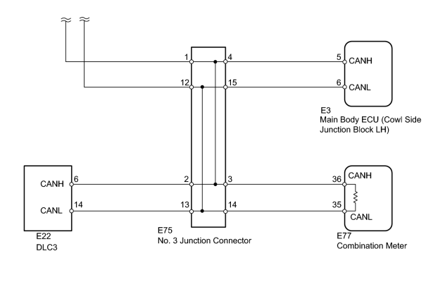
- Main body ECU (cowl side junction block LH)
- AFS ECU (headlight swivel ECU assembly)
- Network gateway ECU
| Last Modified: 11-27-2007 | 1.6 J | |
| Service Category: Power Source/Network | Section: Networking | |
| Model Year: 2008 | Model: LX570 | Doc ID: RM000001YZM00QX |
| Title: NETWORKING: CAN COMMUNICATION SYSTEM: DESCRIPTION (2008 LX570) | ||
|
Open in One Side of CAN Branch Line |
DESCRIPTION
If 2 or more ECUs and/or sensors do not appear on the Techstream "CAN Bus Check" screen, one side of the CAN branch wire may be open (One side of the CANH [branch wire]/CANL [branch wire] of the ECU and/or sensor is open).
|
Symptom |
Trouble Area |
|---|---|
|
2 or more ECUs and/or sensors do not appear on the Techstream "CAN Bus Check" screen. |
|
*1: w/ Navigation System
*2: w/o Navigation System
WIRING DIAGRAM
INSPECTION PROCEDURE
HINT:
- Perform the following inspection for the ECUs (sensors) which are not displayed on the Techstream. If a malfunction cannot be identified, perform the following inspections for the ECUs (sensors) connected to the CAN communication system.
- Do not remove the center airbag sensor and ECM, as they are the end parts of the circuit. If removed, CAN communication will not be possible.
- The open circuit confirmation of the center airbag sensor, ECM and main wire is performed in the Check CAN Bus Line procedure of How to Proceed with Troubleshooting. This inspection only has procedures for checking for an open circuit on one side of the CAN branch wire.
PROCEDURE
|
1. |
DISCONNECT CABLE FROM NEGATIVE BATTERY TERMINAL |
(a) Disconnect the cable from the negative (-) battery terminal before measuring the resistances of the main wire and the branch wire.
CAUTION:
Wait at least 90 seconds after disconnecting the cable from the negative (-) battery terminal to disable the SRS system.
NOTICE:
-
w/ Navigation System:
After the engine switch is turned off, the HDD navigation system requires approximately 6 minutes to record various types of memory and settings. As a result, after turning the engine switch off, wait 6 minutes or more before disconnecting the cable from the negative (-) battery terminal.
-
When disconnecting the cable, some systems need to be initialized after the cable is reconnected
 .
.
|

|
2. |
CHECK FOR OPEN IN ONE SIDE OF BRANCH WIRE (DISPLAY AND NAVIGATION MODULE DISPLAY OR MULTI-DISPLAY) |
(a) Disconnect the F28 display and navigation module display*1 or multi-display*2 connector.
*1: w/ Navigation System
*2: w/o Navigation System
(b) Select "CAN Bus Check" on the Techstream
.
Result
|
Result |
Proceed to |
|---|---|
|
"AVN" not displayed on the Techstream. |
A |
|
Several ECUs and sensors other than "AVN" not displayed on the Techstream. |
B |
|
|
3. |
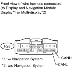
CHECK FOR OPEN IN ONE SIDE OF BRANCH WIRE (DISPLAY AND NAVIGATION MODULE DISPLAY OR MULTI-DISPLAY BRANCH WIRE) |
|
(a) Measure the resistance according to the value(s) in the table below. Standard Resistance:
|
|
|
4. |
CHECK FOR OPEN IN ONE SIDE OF BRANCH WIRE (CENTER AIRBAG SENSOR) |
(a) Disconnect the E47 center airbag sensor connector.
(b) Select "CAN Bus Check" on the Techstream
.
Result
|
Result |
Proceed to |
|---|---|
|
"SRS airbag" not displayed on the Techstream. |
A |
|
Several ECUs and sensors other than "SRS airbag" not displayed on the Techstream. |
B |
|
|
5. |
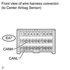
CHECK FOR OPEN IN ONE SIDE OF BRANCH WIRE (CENTER AIRBAG SENSOR BRANCH WIRE) |
|
(a) Measure the resistance according to the value(s) in the table below. Standard Resistance:
|
|
|
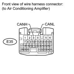
6. |
CHECK FOR OPEN IN ONE SIDE OF BRANCH WIRE (AIR CONDITIONING AMPLIFIER) |
(a) Disconnect the E35 air conditioning amplifier connector.
(b) Select "CAN Bus Check" on the Techstream
.
Result
|
Result |
Proceed to |
|---|---|
|
"Air Conditioner" not displayed on the Techstream. |
A |
|
Several ECUs and sensors other than "Air Conditioner" not displayed on the Techstream. |
B |
|
|
7. |
CHECK FOR OPEN IN ONE SIDE OF BRANCH WIRE (AIR CONDITIONING AMPLIFIER BRANCH WIRE) |
|
(a) Measure the resistance according to the value(s) in the table below. Standard Resistance:
|
|
|
8. |
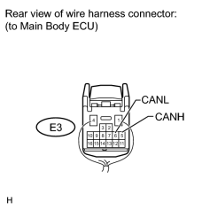
CHECK FOR OPEN IN ONE SIDE OF BRANCH WIRE (MAIN BODY ECU) |
(a) Disconnect the E3 main body ECU (cowl side junction block LH) connector.
(b) Select "CAN Bus Check" on the Techstream
.
Result
|
Result |
Proceed to |
|---|---|
|
"Main Body" not displayed on the Techstream. |
A |
|
Several ECUs and sensors other than "Main Body" not displayed on the Techstream. |
B |
|
|
9. |
CHECK FOR OPEN IN ONE SIDE OF BRANCH WIRE (MAIN BODY ECU BRANCH WIRE) |
|
(a) Measure the resistance according to the value(s) in the table below. Standard Resistance:
|
|
|
10. |
CHECK FOR OPEN IN ONE SIDE OF CAN BRANCH WIRE (AFS ECU) |
(a) Disconnect the E91 AFS ECU (headlight swivel ECU) connector.
(b) Select "CAN Bus Check" on the Techstream
.
Result
|
Result |
Proceed to |
|---|---|
|
"AFS/HL AutoLeveling" not displayed on the Techstream. |
A |
|
Several ECUs and sensors other than "AFS/HL AutoLeveling" not displayed on the Techstream. |
B |
|
|
11. |
CHECK FOR OPEN IN ONE SIDE OF CAN BRANCH WIRE (AFS ECU BRANCH WIRE) |
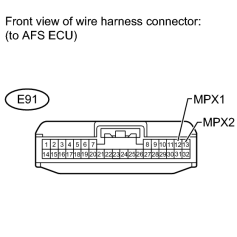
(a) Measure the resistance according to the value(s) in the table below.
Standard Resistance:
|
Tester Connection |
Switch Condition |
Specified Condition |
|---|---|---|
|
E91-12 (MPX1) - E91-13 (MPX2) |
Engine switch off |
54 to 69 Ω |
|
|
12. |
CHECK FOR OPEN IN ONE SIDE OF BRANCH WIRE (NETWORK GATEWAY ECU BRANCH WIRE) |
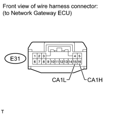
(a) Disconnect the E31 network gateway ECU connector.
(b) Measure the resistance according to the value(s) in the table below.
Standard Resistance:
|
Tester Connection |
Switch Condition |
Specified Condition |
|---|---|---|
|
E31-16 (CA1H) - E31-15 (CA1L) |
Engine switch off |
54 to 69 Ω |
|

|

|