Home Power Source/Network Battery/Charging POWER OUTLETS (EXT): TOWING CONVERTER RELAY
Last Modified: 11-27-2007 1.6 G
Service Category: Power Source/Network Section: Battery/Charging
Model Year: 2008 Model: LX570 Doc ID: RM0000024JA007X
Title: POWER OUTLETS (EXT): TOWING CONVERTER RELAY: ON-VEHICLE INSPECTION (2008 LX570)

ON-VEHICLE INSPECTION

1. INSPECT TOWING CONVERTER RELAY
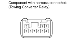

(a) Measure the voltage according to the value(s) in the table below.

Standard Voltage:

Tester Connection

Switch Condition

Specified Condition

1 - Body Ground

Always

11 to 14 V

2 - Body Ground

Turn signal switch (right turn) Off → On

0 V → 11 to 14 V (60 to 120 times per minute)

2 - Body Ground

Brake pedal depressed

11 to 14 V

2 - Body Ground

Turn signal (right turn) Off → On while depressing brake pedal

0 V → 11 to 14 V (60 to 120 times per minute)

3 - Body Ground

Turn signal switch (right turn) Off → On

0 V → 11 to 14 V (60 to 120 times per minute)

4 - Body Ground

Turn signal switch (left turn) Off → On

0 V → 11 to 14 V (60 to 120 times per minute)

4 - Body Body Ground

Brake pedal depressed

11 to 14 V

4 - Body Body Ground

Turn signal (left turn) Off → On while depressing brake pedal

0 V → 11 to 14 V (60 to 120 times per minute)

8 - Body Ground

Brake pedal depressed

11 to 14 V

9 - Body Ground

Turn signal switch (left turn) Off → On

0 V → 11 to 14 V (60 to 120 times per minute)

If the result is not as specified, there may be a malfunction in the wire harness or towing converter relay.

(b) Measure the resistance according to the value(s) in the table below.

Standard Resistance:

Tester Connection

Condition

Specified Condition

6 - Body Ground

Always

Below 1 Ω

If the result is not as specified, there may be a malfunction in the wire harness or towing converter relay.

2. INSPECT TOWING CONVERTER RELAY (SUB BATT)
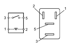

(a) Measure the resistance according to the value(s) in the table below.

Standard Resistance:

Tester Connection

Condition

Specified Condition

3 - 5

Battery voltage not applied between terminals 1 and 2

10 kΩ or higher

Battery voltage applied to terminals 1 and 2

Below 1 Ω

If the result is not as specified, replace the relay.

3. INSPECT TOWING CONVERTER RELAY (TOW TAIL)


(a) Measure the resistance according to the value(s) in the table below.

Standard Resistance:

Tester Connection

Condition

Specified Condition

3 - 5

Battery voltage not applied between terminals 1 and 2

10 kΩ or higher

Battery voltage applied to terminals 1 and 2

Below 1 Ω

If the result is not as specified, replace the relay.