| Last Modified: 11-27-2007 | 1.6 J | |
| Service Category: Vehicle Exterior | Section: Door/Hatch | |
| Model Year: 2008 | Model: LX570 | Doc ID: RM0000025WO003X |
| Title: DOOR / HATCH: POWER BACK DOOR SYSTEM: DESCRIPTION (2008 LX570) | ||
|
ECU Power Source Circuit |
DESCRIPTION
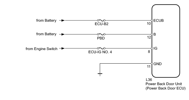
This circuit supplies power to operate the power back door unit.
WIRING DIAGRAM
INSPECTION PROCEDURE
PROCEDURE
|
1. |
INSPECT FUSE (ECU-B2, PBD, ECU-IG4) |
(a) Remove the ECU-B2 and PBD fuses from the engine room relay block.
(b) Remove the ECU-IG4 fuse from the cowl side junction block RH.
(c) Measure the resistance according to the value(s) in the table below.
Standard Resistance:
|
Tester Connection |
Condition |
Specified Condition |
|---|---|---|
|
ECU-B2 fuse |
Always |
Below 1 Ω |
|
PBD fuse |
Always |
Below 1 Ω |
|
ECU-IG4 fuse |
Always |
Below 1 Ω |
|

|
2. |
CHECK HARNESS AND CONNECTOR (UNIT - BATTERY AND BODY GROUND) |
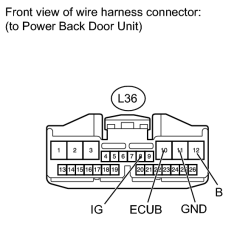
(a) Disconnect the L36 unit connector.
(b) Measure the voltage according to the value(s) in the table below.
Standard Voltage:
|
Tester Connection |
Condition |
Specified Condition |
|---|---|---|
|
L36-10 (ECUB) - Body ground |
Always |
11 to 14 V |
|
L36-12 (B) - Body ground |
Always |
11 to 14 V |
|
L36-8 (IG) - Body ground |
Engine switch on (IG) |
11 to 14 V |
|
L36-8 (IG) - Body ground |
Engine switch off |
Below 1 V |
(c) Measure the resistance according to the value(s) in the table below.
Standard Resistance:
|
Tester Connection |
Condition |
Specified Condition |
|---|---|---|
|
L36-11 (GND) - Body ground |
Always |
Below 1 Ω |
|

|

|