- Cooler compressor assembly (A/C lock sensor)
- Compressor drive belt
- Harness or connector between cooler compressor assembly and air conditioning amplifier assembly
- Air conditioning amplifier assembly
- CAN communication line
| Last Modified: 11-27-2007 | 1.6 C | |
| Service Category: Vehicle Interior | Section: Heating/Air Conditioning | |
| Model Year: 2008 | Model: LX570 | Doc ID: RM0000026BV00UX |
| Title: HEATING / AIR CONDITIONING: AIR CONDITIONING SYSTEM: SYSTEM DESCRIPTION (2008 LX570) | ||
|
DTC |
B1422/22 |
Compressor Lock Sensor Circuit |
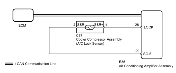
SYSTEM DESCRIPTION
The ECM sends the engine speed signal to the air conditioning amplifier assembly via CAN communication.
The air conditioning amplifier assembly reads the difference between compressor speed and engine speed. When the difference becomes too large, the air conditioning amplifier assembly determines that the compressor is locked, and turns the magnetic clutch off.
|
DTC Code |
DTC Detection Condition |
Trouble Area |
|---|---|---|
|
B1422/22 |
An open or short in the compressor lock sensor circuit. |
|
WIRING DIAGRAM
INSPECTION PROCEDURE
PROCEDURE
|
1. |
CHECK CAN COMMUNICATION SYSTEM |
(a) Use the Techstream to check if the CAN communication system is functioning normally.
Result
|
Result |
Proceed to |
|---|---|
|
CAN DTC is not output |
A |
|
CAN DTC is output |
B |
|

|
2. |
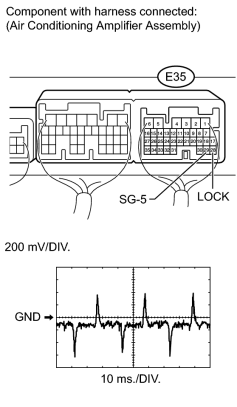
INSPECT AIR CONDITIONING AMPLIFIER ASSEMBLY |
|
(a) Remove the air conditioning amplifier assembly with its connectors still connected
|

(b) Measure the waveform of the connector.
Measurement Condition
|
Item |
Content |
|---|---|
|
Terminal No. (Symbol) |
E35-28 (LOCK) - E35-29 (SG-5) |
|
Tool Setting |
200 mV/DIV., 10 ms/DIV. |
|
Condition |
Engine running A/C switch on Blower switch lo |
OK:
Waveform is as shown in the illustration.
|
|
3. |
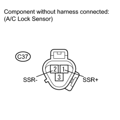
INSPECT COOLER COMPRESSOR ASSEMBLY (A/C LOCK SENSOR) |
|
(a) Disconnect the C37 cooler compressor assembly connector. |
(b) Measure the resistance according to the value(s) in the table below.
Standard Resistance:
|
Tester Connection |
Condition |
Specified Condition |
|---|---|---|
|
C37-1 (SSR+) - C37-2 (SSR-) |
20°C (68°F) |
65 to 125 Ω |
|
|
4. |
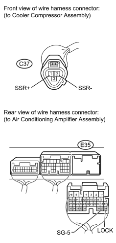
CHECK HARNESS AND CONNECTOR (AIR CONDITIONING AMPLIFIER - COOLER COMPRESSOR) |
|
(a) Disconnect the E35 amplifier connector. |
(b) Disconnect the C37 cooler compressor assembly connector.
(c) Measure the resistance according to the value(s) in the table below.
Standard Resistance:
|
Tester Connection |
Condition |
Specified Condition |
|---|---|---|
|
E35-28 (LOCK) - C37-1 (SSR+) |
Always |
Below 1 Ω |
|
E35-29 (SG-5) - C37-2 (SSR-) |
||
|
E35-28 (LOCK) - Body ground |
Always |
10 kΩ or higher |
|
E35-29 (SG-5) - Body ground |
Always |
Below 1 Ω |
|

|

|