| Last Modified: 11-27-2007 | 1.6 U | |
| Service Category: Vehicle Interior | Section: Theft Deterrent/Keyless Entry | |
| Model Year: 2008 | Model: LX570 | Doc ID: RM0000027YN00CX |
| Title: THEFT DETERRENT / KEYLESS ENTRY: SMART ACCESS SYSTEM WITH PUSH-BUTTON START (for Start Function): TERMINALS OF ECU (2008 LX570) | ||
TERMINALS OF ECU
1. CHECK MAIN BODY ECU (COWL SIDE JUNCTION BLOCK LH)
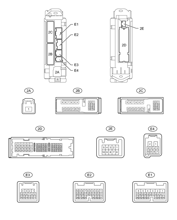
(a) Disconnect the E1, E2 and 2D main body ECU connectors.
(b) Measure the voltage and resistance according to the value(s) in the table below.
|
Terminal No. (Symbol) |
Wiring Color |
Terminal Description |
Condition |
Specified Condition |
|---|---|---|---|---|
|
E1-6 (AM1) - Body ground |
W - Body ground |
+B power supply |
Always |
11 to 14 V |
|
E2-1 (AM2) - Body ground |
W - Body ground |
+B power supply |
Always |
11 to 14 V |
|
E1-17 (SSW1) - Body ground |
B - Body ground |
Engine switch 1 input |
Engine switch pushed |
Below 1 Ω |
|
E1-17 (SSW1) - Body ground |
B - Body ground |
Engine switch 1 input |
Engine switch not pushed |
10 kΩ or higher |
|
E1-16 (SSW2) - Body ground |
B - Body ground |
Engine switch 2 input |
Engine switch pushed |
Below 1 Ω |
|
E1-16 (SSW2) - Body ground |
B - Body ground |
Engine switch 2 input |
Engine switch not pushed |
10 kΩ or higher |
|
2D-62 (GND2) - Body ground |
W-B - Body ground |
Ground |
Always |
Below 1 Ω |
|
2D-20 (LIN1) - Body ground |
GR - Body ground |
LIN line |
Always |
10 kΩ or higher |
If the result is not as specified, there may be a malfunction on the wire harness side.
(c) Reconnect the E1, E2 and 2D main body ECU connectors.
(d) Measure the voltage according to the value(s) in the table below.
|
Terminal No. (Symbol) |
Wiring Color |
Terminal Description |
Condition |
Specified Condition |
|---|---|---|---|---|
|
E1-22 (ACCD) - 2D-62 (GND2) |
P - W-B |
ACC relay drive signal |
Engine switch on (ACC) |
11 to 14 V |
|
E1-22 (ACCD) - 2D-62 (GND2) |
P - W-B |
ACC relay drive signal |
Engine switch off |
Below 1 V |
|
E1-3 (IG1D) - 2D-62 (GND2) |
G - W-B |
IG1 No. 3 relay drive signal |
Engine switch on (IG) |
11 to 14 V |
|
E1-3 (IG1D) - 2D-62 (GND2) |
G - W-B |
IG1 No. 3 relay drive signal |
Engine switch on (ACC) |
Below 1 V |
|
E2-11 (IG2D) - 2D-62 (GND2) |
B - W-B |
Integration relay (IG2 relay) drive signal |
Engine switch on (IG) |
11 to 14 V |
|
E2-11 (IG2D) - 2D-62 (GND2) |
B - W-B |
Integration relay (IG2 relay) drive signal |
Engine switch on (ACC) |
Below 1 V |
|
E1-19 (SLR+) - 2D-62 (GND2) |
G - W-B |
Steering lock power supply |
Steering lock motor operating |
Below 1 V |
|
E1-19 (SLR+) - 2D-62 (GND2) |
G - W-B |
Steering lock power supply |
Steering lock motor not operating |
11 to 14 V |
|
E1-8 (STR) - 2D-62 (GND2) |
L - W-B |
Park/neutral position switch signal |
Engine switch on (IG), shift lever not in P or N → P or N |
Below 2 V → Pulse generation*1 |
|
E1-18 (SLP) - 2D-62 (GND2) |
SB - W-B |
Steering lock actuator position signal |
Steering lock locked |
11 to 14 V |
|
E1-18 (SLP) - 2D-62 (GND2) |
SB - W-B |
Steering lock actuator position signal |
Steering lock released |
Below 1 V |
|
E3-9 (SPD) - 2D-62 (GND2) |
V - W-B |
Speed signal from combination meter |
Engine switch on (IG), driving wheel rotating slowly |
Pulse generation (see waveform 1) |
|
E3-8 (TACH) - 2D-62 (GND2) |
W - W-B |
Tachometer signal |
Engine running |
Pulse generation (see waveform 2) |
|
E4-2 (P) - 2D-62 (GND2) |
L - W-B |
Shift lock signal |
Shift lever in P |
Pulse generation (see waveform 3) |
|
E4-2 (P) - 2D-62 (GND2) |
L - W-B |
Shift lock signal |
Shift lever not in P |
Below 1 V |
|
E4-4 (STSW) - 2D-62 (GND2) |
R - W-B |
Starter activation request signal |
Brake pedal depressed with shift lever in P, engine switch pushed once |
11 to 14 V |
|
E1-15 (INDS) - 2D-62 (GND2) |
W - W-B |
Vehicle condition signal |
Brake pedal released with shift lever in P or N, engine switch off, on (ACC) or on (IG) |
9 to 14 V |
|
E1-14 (INDW) - 2D-62 (GND2) |
W - W-B |
Vehicle condition signal |
Brake pedal released with shift lever in P or N, engine switch off, on (ACC) or on (IG) |
9 to 14 V |
|
E1-25 (SWIL) - 2D-62 (GND2) |
R - W-B |
Illumination signal |
Light control switch tail or head |
11 to 14 V |
|
2B-22 (STP) - 2D-62 (GND2) |
R - W-B |
Stop light switch signal |
Brake pedal depressed |
11 to 14 V |
|
2B-22 (STP) - 2D-62 (GND2) |
R - W-B |
Stop light switch signal |
Brake pedal released |
Below 1 V |
HINT:
*1: Remove the ST CUT relay before measuring the voltage.
If the result is not as specified, the ECU may have a malfunction.
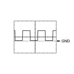
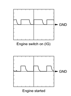
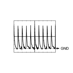
(e) Using an oscilloscope, check the signal waveform of the ECU.
|
(1) Waveform 1
HINT:
As the vehicle speed increases, the wavelength shortens. |
|
(2) Waveform 2
|
|
(3) Waveform 3
|
2. CHECK CERTIFICATION ECU (SMART KEY ECU ASSEMBLY)

(a) Disconnect the E29 certification ECU (smart key ECU assembly) connector.
(b) Measure the voltage and resistance according to the value(s) in the table below.
|
Terminal No. (Symbol) |
Wiring Color |
Terminal Description |
Condition |
Specified Condition |
|---|---|---|---|---|
|
E29-1 (+B) - Body ground |
B - Body ground |
+B power supply |
Always |
11 to 14 V |
|
E29-10 (LIN) - Body ground |
GR - Body ground |
LIN line |
Always |
10 kΩ or higher |
|
E29-17 (E) - Body ground |
W-B - Body ground |
Ground |
Always |
Below 1 Ω |
If the result is not as specified, there may be a malfunction on the wire harness side.
(c) Reconnect the E29 certification ECU (smart key ECU assembly) connector.
(d) Measure the voltage according to the value(s) in the table below.
|
Terminal No. (Symbol) |
Wiring Color |
Terminal Description |
Condition |
Specified Condition |
|---|---|---|---|---|
|
E29-18 (IG) - Body ground |
B - Body ground |
Ignition power supply |
Engine switch on (IG) |
11 to 14 V |
|
E29-18 (IG) - Body ground |
B - Body ground |
Ignition power supply |
Engine switch off |
Below 1 V |
If the result is not as specified, the certification ECU (smart key ECU assembly) may have a malfunction.
3. CHECK ECM
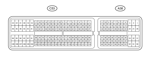
(a) Disconnect the A38 and C53 ECM connectors.
(b) Measure the voltage and resistance according to the value(s) in the table below.
|
Terminal No. (Symbol) |
Wiring Color |
Terminal Description |
Condition |
Specified Condition |
|---|---|---|---|---|
|
A38-1 (BATT) - C53-81 (E1) |
L - W-B |
Battery (for measuring battery voltage and for ECM memory) |
Always |
11 to 14 V |
|
A38-3 (+B) - C53-81 (E1) |
B - W-B |
Power source of ECM |
Engine switch on (IG) |
11 to 14 V |
|
A38-28 (IGSW) - C53-81 (E1) |
B - W-B |
Engine switch signal |
Always |
11 to 14 V |
|
C53-81 (E1) - Body ground |
W-B - Body ground |
Ground |
Always |
Below 1 Ω |
|
C53-43 (E01) - Body ground |
W-B - Body ground |
Ground |
Always |
Below 1 Ω |
|
C53-42 (E02) - Body ground |
BR - Body ground |
Ground |
Always |
Below 1 Ω |
|
C53-46 (E03) - Body ground |
W-B - Body ground |
Ground |
Always |
Below 1 Ω |
|
C53-23 (E04) - Body ground |
W-B - Body ground |
Ground |
Always |
Below 1 Ω |
|
C53-21 (E05) - Body ground |
W-B - Body ground |
Ground |
Always |
Below 1 Ω |
If the result is not as specified, there may be a malfunction on the wire harness side.
(c) Reconnect the ECM connectors.
(d) Measure the voltage according to the value(s) in the table below.
|
Terminal No. (Symbol) |
Wiring Color |
Terminal Description |
Condition |
Specified Condition |
|---|---|---|---|---|
|
A38-46 (STA) - C53-81 (E1) |
R-B - W-B |
ST relay operation signal |
Cranking |
5.5 V or higher |
|
A38-14 (STSW) - C53-81 (E1) |
R - W-B |
Starter activation request signal |
Brake pedal depressed, engine switch on (IG) |
Output voltage at terminal AM1 or AM2 is -2 V or higher |
|
A38-41 (ACCR) - C53-81 (E1) |
L-Y - W-B |
ACC relay cut signal (output) |
Engine switch on (IG) → Cranking |
11 to 14 V → Below 1 V |
|
A38-15 (TACH) - C53-81 (E1) |
W-G - W-B |
Engine speed signal (output) |
Idling |
Pulse generation (see waveform 1) |
|
C53-16 (STAR) - C53-81 (E1) |
L - W-B |
ST relay drive signal |
Cranking |
11 to 14 V |
If the result is not as specified, the ECM may have a malfunction.
|
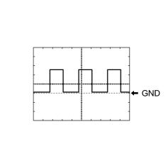
(e) Using an oscilloscope, check the signal waveform of the ECM.
HINT:
As the engine speed increases, the wavelength shortens. |
4. CHECK STEERING LOCK ECU

(a) Disconnect the E26 steering lock ECU connector.
(b) Measure the voltage and resistance according to the value(s) in the table below.
|
Terminal No. (Symbol) |
Wiring Color |
Terminal Description |
Condition |
Specified Condition |
|---|---|---|---|---|
|
E26-7 (B) - Body ground |
R - Body ground |
+B power supply |
Always |
11 to 14 V |
|
E26-6 (IG2) - Body ground |
B - Body ground |
Ignition power supply |
Engine switch on (IG) |
11 to 14 V |
|
E26-6 (IG2) - Body ground |
B - Body ground |
Ignition power supply |
Engine switch off |
Below 1 V |
|
E26-1 (GND) - Body ground |
W-B - Body ground |
Ground |
Always |
Below 1 Ω |
|
E26-2 (SGND) - Body ground |
BR - Body ground |
Ground |
Always |
Below 1 Ω |
If the result is not as specified, there may be a malfunction on the wire harness side.
(c) Reconnect the E26 steering lock ECU connector.
(d) Measure the voltage according to the value(s) in the table below.
|
Terminal No. (Symbol) |
Wiring Color |
Terminal Description |
Condition |
Specified Condition |
|---|---|---|---|---|
|
E26-4 (SLP1) - E26-1 (GND) |
SB - W-B |
Steering lock actuator position signal |
Steering locked |
11 to 14 V |
|
E26-4 (SLP1) - E26-1 (GND) |
SB - W-B |
Steering lock actuator position signal |
Steering released |
Below 1 V |
If the result is not as specified, the ECU may have a malfunction.

|

|