- Sliding roof drive gear sub-assembly (Sliding roof ECU)
- Map light assembly (Sliding roof switch)
- Harness or connector
| Last Modified: 11-27-2007 | 1.6 C | |
| Service Category: Vehicle Exterior | Section: Sliding Roof/Convertible | |
| Model Year: 2008 | Model: LX570 | Doc ID: RM0000029GI016X |
| Title: SLIDING ROOF / CONVERTIBLE: SLIDING ROOF SYSTEM: DESCRIPTION (2008 LX570) | ||
|
DTC |
B2343 |
Position Initialization Incomplete |
DESCRIPTION
This DTC is output when the sliding roof drive gear (sliding roof ECU) has not been initialized.
|
DTC Code |
DTC Detection Condition |
Trouble Area |
|---|---|---|
|
B2343 |
The sliding roof drive gear (sliding roof ECU) has not been initialized. |
|
WIRING DIAGRAM
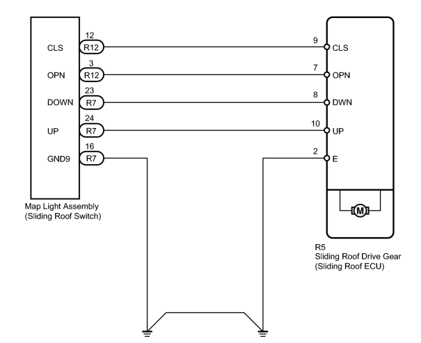
INSPECTION PROCEDURE
PROCEDURE
|
1. |
INITIALIZE SLIDING ROOF DRIVE GEAR SUB-ASSEMBLY (SLIDING ROOF ECU) |
(a) Check that the sliding roof drive gear can be initialized
 .
.
OK:
Sliding roof drive gear can be initialized.
|

|
2. |
CHECK FOR DTC |
(a) Clear the DTCs
.
(b) Check the DTCs
.
Result
|
Result |
Proceed to |
|---|---|
|
No DTC is output |
A |
|
DTC B2343 is output |
B |
|
|
3. |
CHECK HARNESS AND CONNECTOR (SLIDING ROOF DRIVE GEAR - MAP LIGHT) |
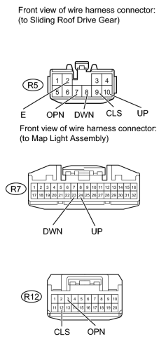
(a) Disconnect the R5 drive gear connector.
(b) Disconnect the R7 and R12 map light connectors.
(c) Measure the resistance according to the value(s) in the table below.
Standard Resistance:
|
Tester Connection |
Condition |
Specified Condition |
|---|---|---|
|
R5-10 (UP) - R7-24 (UP) |
Always |
Below 1 Ω |
|
R5-8 (DWN) - R7-23 (DOWN) |
Always |
Below 1 Ω |
|
R5-7 (OPN) - R12-3 (OPN) |
Always |
Below 1 Ω |
|
R5-9 (CLS) - R12-12 (CLS) |
Always |
Below 1 Ω |
|
R7-16 (GND9) - Body ground |
Always |
Below 1 Ω |
|
R5-2 (E) - Body ground |
Always |
Below 1 Ω |
|
R5-10 (UP) or R7-24 (UP) - Body ground |
Always |
10 kΩ or higher |
|
R5-8 (DWN) or R7-23 (DOWN) - Body ground |
Always |
10 kΩ or higher |
|
R5-7 (OPN) or R12-3 (OPN) - Body ground |
Always |
10 kΩ or higher |
|
R5-9 (CLS) or R12-12 (CLS) - Body ground |
Always |
10 kΩ or higher |
|
|
4. |
INSPECT MAP LIGHT ASSEMBLY (SLIDING ROOF SWITCH) |
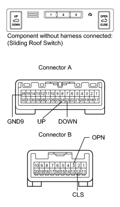
(a) Remove the map light
.
(b) Measure the resistance according to the value(s) in the table below.
Standard Resistance:
|
Tester Connection |
Switch Condition |
Specified Condition |
|---|---|---|
|
A-24 (UP) - A-16 (GND9) |
UP switch is pressed |
Below 1 Ω |
|
A-24 (UP) - A-16 (GND9) |
UP switch is not pressed |
10 kΩ or higher |
|
A-23 (DOWN) - A-16 (GND9) |
DOWN switch is pressed |
Below 1 Ω |
|
A-23 (DOWN) - A-16 (GND9) |
DOWN switch is not pressed |
10 kΩ or higher |
|
B-3 (OPN) - A-16 (GND9) |
OPEN switch is pressed |
Below 1 Ω |
|
B-3 (OPN) - A-16 (GND9) |
OPEN switch is not pressed |
10 kΩ or higher |
|
B-12 (CLS) - A-16 (GND9) |
CLOSE switch is pressed |
Below 1 Ω |
|
B-12 (CLS) - A-16 (GND9) |
CLOSE switch is not pressed |
10 kΩ or higher |
|

|

|