| Last Modified: 11-27-2007 | 1.6 J | |
| Service Category: Vehicle Exterior | Section: Door/Hatch | |
| Model Year: 2008 | Model: LX570 | Doc ID: RM000002AE0005X |
| Title: DOOR / HATCH: POWER BACK DOOR SYSTEM: DESCRIPTION (2008 LX570) | ||
|
Power Back Door Sensor Circuit |
DESCRIPTION
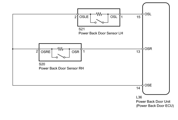
When the power back door unit (power back door ECU) receives a jam signal from the power back door sensor while the power back door closer is operating, the ECU reverses the back door operation and opens the door.
WIRING DIAGRAM
INSPECTION PROCEDURE
PROCEDURE
|
1. |
READ VALUE USING TECHSTREAM (POWER BACK DOOR SENSOR ASSEMBLY) |
(a) Check the Data List for proper functioning of the power back door sensor.
Back Door
|
Tester Display |
Measurement Item/Range |
Normal Condition |
Diagnostic Note |
|---|---|---|---|
|
PBD power back door sensor (Left) |
Power back door sensor LH signal/ON or OFF |
ON: Power back door sensor LH pressed OFF: Power back door sensor LH not pressed |
- |
|
PBD power back door sensor (Right) |
Power back door sensor RH signal/ON or OFF |
ON: Power back door sensor RH pressed OFF: Power back door sensor RH not pressed |
- |
OK:
The display is as specified in the normal condition.
|

|
2. |
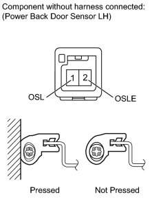
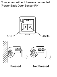
INSPECT POWER BACK DOOR SENSOR ASSEMBLY |
|
(a) for LH: (1) Disconnect the S21 sensor connector. (2) Measure the resistance according to the value(s) in the table below. Standard Resistance:
|
|
(b) for RH: (1) Disconnect the S20 sensor connector. (2) Measure the resistance according to the value(s) in the table below. Standard Resistance:
|
|
|
3. |
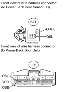
CHECK HARNESS AND CONNECTOR (SENSOR - UNIT AND BODY GROUND) |
|
(a) for LH: (1) Disconnect the S21 sensor connector. (2) Disconnect the L36 ECU connector. (3) Measure the resistance according to the value(s) in the table below. Standard Resistance:
|
|
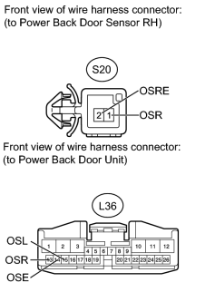
(b) for RH: (1) Disconnect the S20 sensor connector. (2) Disconnect the L36 ECU connector. (3) Measure the resistance according to the value(s) in the table below. Standard Resistance:
|
|

|

|