- The multiplex network master switch is stuck.
- The multiplex network master switch is held in the same position for more than 20 sec.
| Last Modified: 11-27-2007 | 1.6 C | |
| Service Category: Vehicle Exterior | Section: Window/Glass | |
| Model Year: 2008 | Model: LX570 | Doc ID: RM000002BQR00HX |
| Title: WINDOW / GLASS: POWER WINDOW CONTROL SYSTEM: DESCRIPTION (2008 LX570) | ||
|
DTC |
B2312 |
Power Window Switch Malfunction |
DESCRIPTION
The power window regulator motor consists of the motor, regulator and ECU. The power window regulator motor is driven by operating the power window switch.
This DTC is stored when the ECU built into the regulator motor determines that the power window switch is stuck.
HINT:
This DTC may be stored for all the windows.
NOTICE:
- When the power window regulator motor is reinstalled or replaced, the power window control system must be initialized.
-
After a door glass or a door glass run has been replaced, the jam protection function may operate unexpectedly when the auto up function is used. In such cases, the auto up function can be resumed by repeating the following operation at least 5 times:
- Close the power window by fully pulling up the power window switch and holding it in the auto up position.
- Open the power window by fully pushing down the power window switch.
Multiplex Network Master Switch
|
DTC Code |
DTC Detection Condition |
Trouble Area |
|---|---|---|
|
B2312 |
|
|
Front Power Window Regulator Motor LH
|
DTC Code |
DTC Detection Condition |
Trouble Area |
|---|---|---|
|
B2312 |
|
|
Front Power Window Regulator Motor RH
|
DTC Code |
DTC Detection Condition |
Trouble Area |
|---|---|---|
|
B2312 |
|
|
Rear Power Window Regulator Motor LH
|
DTC Code |
DTC Detection Condition |
Trouble Area |
|---|---|---|
|
B2312 |
|
|
Rear Power Window Regulator Motor RH
|
DTC Code |
DTC Detection Condition |
Trouble Area |
|---|---|---|
|
B2312 |
|
|
WIRING DIAGRAM
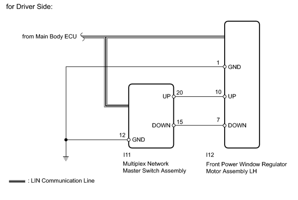
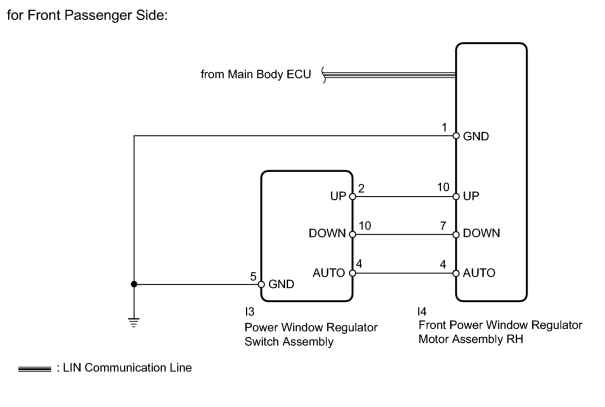
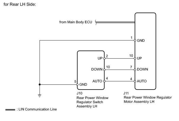
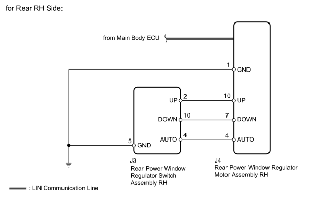
INSPECTION PROCEDURE
PROCEDURE
|
1. |
CLEAR DTC |
(a) Clear the DTCs
 .
.
|

|
2. |
CHECK FOR DTC |
(a) Check for DTCs
.
Result
|
Result |
Proceed to |
|---|---|
|
B2312 is output. |
A |
|
LIN communication DTCs are output. |
B |
|
No DTCs are output. |
C |
|
|
3. |
CHECK MALFUNCTION LOCATION |
(a) Check where DTC B2312 is output from.
Result
|
Result |
Proceed to |
|---|---|
|
B2312 is output from multiplex network master switch. |
A |
|
B2312 is output from front power window regulator motor LH. |
B |
|
B2312 is output from front power window regulator motor RH. |
C |
|
B2312 is output from rear power window regulator motor LH. |
D |
|
B2312 is output from rear power window regulator motor RH. |
E |
|
|
4. |
READ VALUE USING TECHSTREAM (FRONT POWER WINDOW REGULATOR MOTOR LH) |
(a) Use the Data List to check if the power window regulator motor is functioning properly
.
D-Door Motor
|
Tester Display |
Measurement Item/Range |
Normal Condition |
Diagnostic Note |
|---|---|---|---|
|
D Door P/W Auto SW |
Driver side power window auto up/down signal / ON or OFF |
ON: Driver side power window auto up/down switch operated OFF: Driver side power window switch not operated |
- |
|
D Door P/W Up SW |
Driver side power window manual up signal / ON or OFF |
ON: Driver side power window manual up switch operated OFF: Driver side power window switch not operated |
- |
|
D Door P/W Down SW |
Driver side power window manual down signal / ON or OFF |
ON: Driver side power window manual down switch operated OFF: Driver side power window switch not operated |
- |
OK:
Techstream display changes according to operation of multiplex network master switch.
|
|
5. |
CHECK HARNESS AND CONNECTOR (MULTIPLEX NETWORK MASTER SWITCH - FRONT POWER WINDOW REGULATOR MOTOR LH) |
|
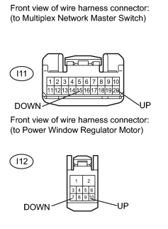
(a) Disconnect I11 switch connector. |
(b) Disconnect I12 motor connector.
(c) Measure the resistance according to the value(s) in the table below.
Standard Resistance:
|
Tester Connection |
Condition |
Specified Condition |
|---|---|---|
|
I11-20 (UP) - I12-10 (UP) |
Always |
Below 1 Ω |
|
I11-15 (DOWN) - I12-7 (DOWN) |
Always |
Below 1 Ω |
|
I11-20 (UP) or I12-10 (UP) - Body ground |
Always |
10 kΩ or higher |
|
I11-15 (DOWN) or I12-7 (DOWN) - Body ground |
Always |
10 kΩ or higher |
|
|
6. |
READ VALUE USING TECHSTREAM (FRONT POWER WINDOW REGULATOR MOTOR RH) |
(a) Use the Data List to check if the power window regulator motor is functioning properly
.
P-Door Motor
|
Tester Display |
Measurement Item/Range |
Normal Condition |
Diagnostic Note |
|---|---|---|---|
|
P Door P/W Auto SW |
Front passenger side power window auto up/down signal / ON or OFF |
ON: Front passenger side power window auto up/down switch operated OFF: Power window regulator switch not operated |
- |
|
P Door P/W Up SW |
Front passenger side power window manual up signal / ON or OFF |
ON: Front passenger side power window manual up switch operated OFF: Power window regulator switch not operated |
- |
|
P Door P/W Down SW |
Front passenger side power window manual down signal / ON or OFF |
ON: Front passenger side power window manual down switch operated OFF: Power window regulator switch not operated |
- |
OK:
Techstream display changes according to operation of power window regulator switch.
|
|
7. |
INSPECT POWER WINDOW REGULATOR SWITCH |
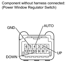
(a) Remove the power window regulator switch
.
(b) Measure the resistance according to the value(s) in the table below.
Standard Resistance:
|
Tester Connection |
Switch Condition |
Specified Condition |
|---|---|---|
|
I3-2 (UP) - I3-5 (GND) |
Manual up operation |
Below 1 Ω |
|
I3-10 (DOWN) - I3-5 (GND) |
Manual down operation |
Below 1 Ω |
|
I3-4 (AUTO) - I3-5 (GND) |
Auto up/down operation |
Below 1 Ω |
|
|
8. |
CHECK HARNESS AND CONNECTOR (POWER WINDOW REGULATOR SWITCH - FRONT POWER WINDOW REGULATOR MOTOR RH) |
|
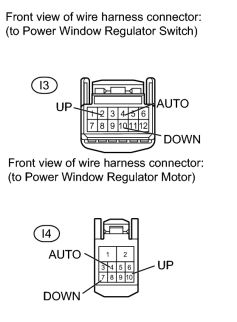
(a) Disconnect the I3 switch connector. |
(b) Disconnect the I4 motor connector.
(c) Measure the resistance according to the value(s) in the table below.
Standard Resistance:
|
Tester Connection |
Condition |
Specified Condition |
|---|---|---|
|
I3-2 (UP) - I4-10 (UP) |
Always |
Below 1 Ω |
|
I3-10 (DOWN) - I4-7 (DOWN) |
Always |
Below 1 Ω |
|
I3-4 (AUTO) - I4-4 (AUTO) |
Always |
Below 1 Ω |
|
I3-2 (UP) or I4-10 (UP) - Body ground |
Always |
10 kΩ or higher |
|
I3-10 (DOWN) or I4-7 (DOWN) - Body ground |
Always |
10 kΩ or higher |
|
I3-4 (AUTO) or I4-4 (AUTO) - Body ground |
Always |
10 kΩ or higher |
|
|
9. |
READ VALUE USING TECHSTREAM (REAR POWER WINDOW REGULATOR MOTOR LH) |
(a) Use the Data List to check if the power window regulator motor is functioning properly
.
RL-Door Motor
|
Tester Display |
Measurement Item/Range |
Normal Condition |
Diagnostic Note |
|---|---|---|---|
|
RL Door P/W Auto SW |
Rear power window LH auto up/down signal / ON or OFF |
ON: Rear power window LH auto up/down switch operated OFF: Rear power window LH switch not operated |
- |
|
RL Door P/W Up SW |
Rear power window LH manual up signal / ON or OFF |
ON: Rear power window LH manual up switch operated OFF: Rear power window LH switch not operated |
- |
|
RL Door P/W Down SW |
Rear power window LH manual down signal / ON or OFF |
ON: Rear power window LH manual down switch operated OFF: The rear power window LH switch not operated |
- |
OK:
Techstream display changes according to operation of rear power window regulator switch LH.
|
|
10. |
INSPECT REAR POWER WINDOW REGULATOR SWITCH LH |
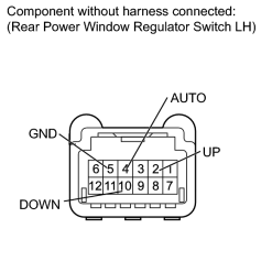
(a) Remove the rear power window regulator switch
.
(b) Measure the resistance according to the value(s) in the table below.
Standard Resistance:
|
Tester Connection |
Switch Condition |
Specified Condition |
|---|---|---|
|
J10-2 (UP) - J10-5 (GND) |
Manual up operation |
Below 1 Ω |
|
J10-10 (DOWN) - J10-5 (GND) |
Manual down operation |
Below 1 Ω |
|
J10-4 (AUTO) - J10-5 (GND) |
Auto up/down operation |
Below 1 Ω |
|
|
11. |
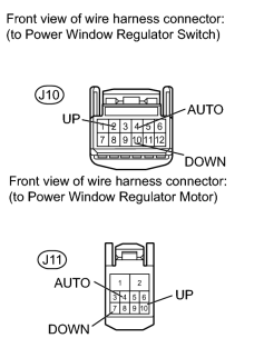
CHECK HARNESS AND CONNECTOR (REAR POWER WINDOW REGULATOR SWITCH LH - REAR POWER WINDOW REGULATOR MOTOR LH) |
|
(a) Disconnect the J10 switch connector. |
(b) Disconnect the J11 motor connector.
(c) Measure the resistance according to the value(s) in the table below.
Standard Resistance:
|
Tester Connection |
Condition |
Specified Condition |
|---|---|---|
|
J10-2 (UP) - J11-10 (UP) |
Always |
Below 1 Ω |
|
J10-10 (DOWN) - J11-7 (DOWN) |
Always |
Below 1 Ω |
|
J10-4 (AUTO) - J11-4 (AUTO) |
Always |
Below 1 Ω |
|
J10-2 (UP) or J11-10 (UP) - Body ground |
Always |
10 kΩ or higher |
|
J10-10 (DOWN) or J11-7 (DOWN) - Body ground |
Always |
10 kΩ or higher |
|
J10-4 (AUTO) or J11-4 (AUTO) - Body ground |
Always |
10 kΩ or higher |
|
|
12. |
READ VALUE USING TECHSTREAM (REAR POWER WINDOW REGULATOR MOTOR RH) |
(a) Use the Data List to check if the power window regulator motor is functioning properly
.
RR-Door Motor
|
Tester Display |
Measurement Item/Range |
Normal Condition |
Diagnostic Note |
|---|---|---|---|
|
RR Door P/W Auto SW |
Rear power window RH auto up/down signal / ON or OFF |
ON: The rear power window RH auto up/down switch operated OFF: The rear power window RH switch not operated |
- |
|
RR Door P/W Up SW |
Rear power window RH manual up signal / ON or OFF |
ON: The rear power window RH manual up switch operated OFF: The rear power window RH switch not operated |
- |
|
RR Door P/W Down SW |
Rear power window RH manual down signal / ON or OFF |
ON: The rear power window RH manual down switch operated OFF: The rear power window RH switch not operated |
- |
OK:
Techstream display changes according to operation of rear power window regulator switch RH.
|
|
13. |
INSPECT REAR POWER WINDOW REGULATOR SWITCH RH |
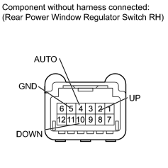
(a) Remove the rear power window regulator switch RH
.
(b) Measure the resistance according to the value(s) in the table below.
Standard Resistance:
|
Tester Connection |
Switch Condition |
Specified Condition |
|---|---|---|
|
J3-2 (UP) - J3-5 (GND) |
Manual up operation |
Below 1 Ω |
|
J3-10 (DOWN) - J3-5 (GND) |
Manual down operation |
Below 1 Ω |
|
J3-4 (AUTO) - J3-5 (GND) |
Auto up/down operation |
Below 1 Ω |
|
|
14. |
CHECK HARNESS AND CONNECTOR (REAR POWER WINDOW REGULATOR SWITCH RH - REAR POWER WINDOW REGULATOR MOTOR RH) |
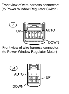
(a) Disconnect the J3 switch connector.
(b) Disconnect the J4 motor connector.
(c) Measure the resistance according to the value(s) in the table below.
Standard Resistance:
|
Tester Connection |
Condition |
Specified Condition |
|---|---|---|
|
J3-2 (UP) - J4-10 (UP) |
Always |
Below 1 Ω |
|
J3-10 (DOWN) - J4-7 (DOWN) |
Always |
Below 1 Ω |
|
J3-4 (AUTO) - J4-4 (AUTO) |
Always |
Below 1 Ω |
|
J3-2 (UP) or J4-10 (UP) - Body ground |
Always |
10 kΩ or higher |
|
J3-10 (DOWN) or J4-7 (DOWN) - Body ground |
Always |
10 kΩ or higher |
|
J3-4 (AUTO) or J4-4 (AUTO) - Body ground |
Always |
10 kΩ or higher |
|

|

|