- Harness or connector
- Speaker
- Stereo component amplifier assembly
| Last Modified: 11-27-2007 | 1.6 C | |
| Service Category: Audio/Visual/Telematics | Section: Audio/Video | |
| Model Year: 2008 | Model: LX570 | Doc ID: RM000002DAR00KX |
| Title: AUDIO / VIDEO: AUDIO AND VISUAL SYSTEM: DESCRIPTION (2008 LX570) | ||
|
DTC |
74-40 |
Short in Speaker Circuit |
DESCRIPTION
|
DTC Code |
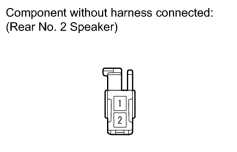
DTC Detection Condition |
Trouble Area |
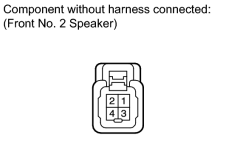
|---|---|---|
|
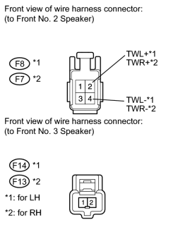
74-40 |
A short is detected in the speaker output circuit. |
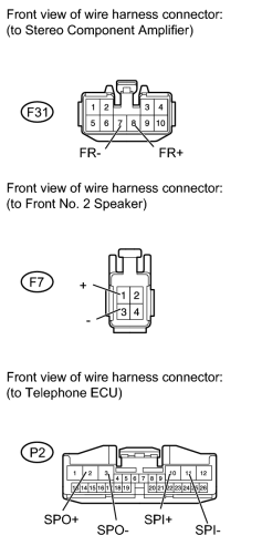
|
WIRING DIAGRAM
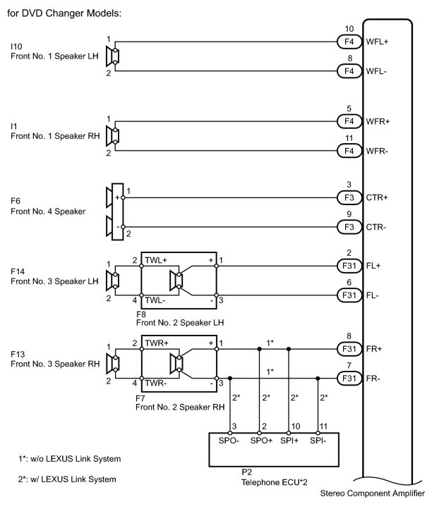
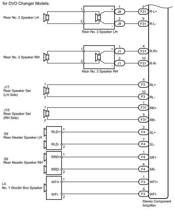
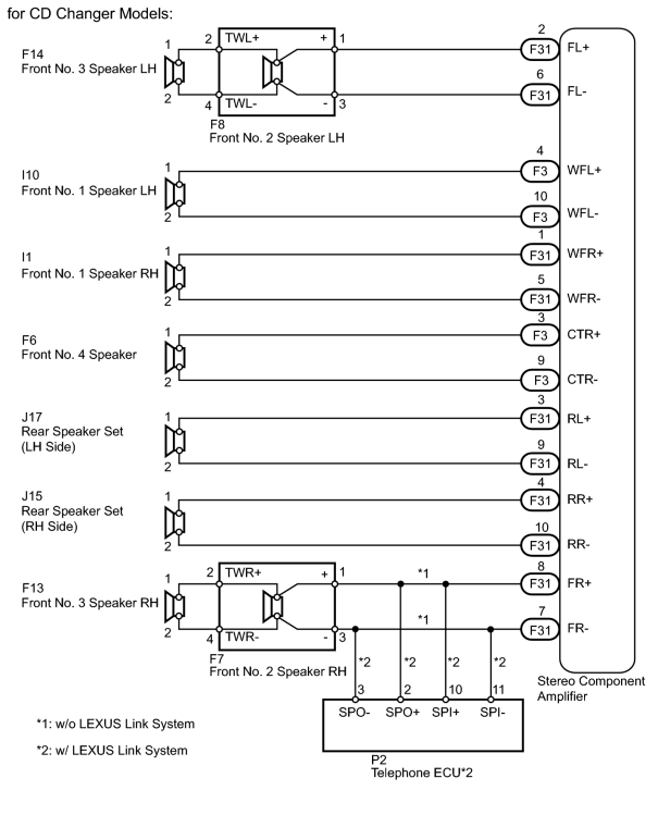
INSPECTION PROCEDURE
HINT:
After the inspection is completed, clear the DTCs.
PROCEDURE
|
1. |
CHECK AUDIO MODELS |
(a) Check the audio model.
Result
|
Result |
Proceed to |
|---|---|
|
DVD changer models |
A |
|
CD changer models |
B |
|

|
2. |
CHECK FOR DTC |
(a) Disconnect the F31, F4 and F3 amplifier connectors.
(b) Clear the DTCs.
(c) Check if DTC 74-40 is output.
OK:
DTC 74-40 is not output.
|
|
3. |
CHECK FOR DTC |
(a) Reconnect the F3 amplifier connector.
(b) Check if DTC 74-40 is output.
OK:
DTC 74-40 is not output.
|
|
4. |
CHECK FOR DTC |
(a) Reconnect the F31 amplifier connector.
(b) Check if DTC 74-40 is output.
OK:
DTC 74-40 is not output.
|
|
5. |
CHECK HARNESS AND CONNECTOR (STEREO COMPONENT AMPLIFIER - SPEAKER) |
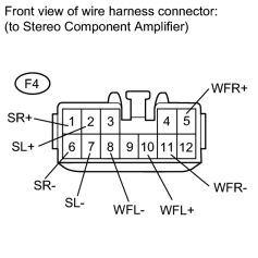
|
(a) Disconnect the F4 amplifier connector. |
(b) Measure the resistance according to the value(s) in the table below.
Standard Resistance:
|
Tester Connection |
Condition |
Specified Condition |
|---|---|---|
|
F4-1 (SR+) - Body ground |
Always |
10 kΩ or higher |
|
F4-2 (SL+) - Body ground |
||
|
F4-5 (WFR+) - Body ground |
||
|
F4-6 (SR-) - Body ground |
||
|
F4-7 (SL-) - Body ground |
||
|
F4-8 (WFL-) - Body ground |
||
|
F4-10 (WFL+) - Body ground |
||
|
F4-11 (WFR-) - Body ground |
|
|
6. |
INSPECT FRONT NO. 1 SPEAKER ASSEMBLY |
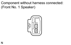
|
(a) Disconnect the I10 and I1 speaker connectors. |
(b) Measure the resistance according to the value(s) in the table below.
Standard Resistance:
|
Tester Connection |
Condition |
Specified Condition |
|---|---|---|
|
1 - 2 |
Always |
1.9 +/-0.4 Ω |
|
|
7. |
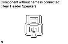
INSPECT REAR HEADER SPEAKER ASSEMBLY |
|
(a) Disconnect the S9 and S8 speaker connectors. |
(b) Measure the resistance according to the value(s) in the table below.
Standard Resistance:
|
Tester Connection |
Condition |
Specified Condition |
|---|---|---|
|
1 - 2 |
Always |
6.0 +/-1.0 Ω |
|
|
8. |
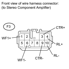
CHECK HARNESS AND CONNECTOR (STEREO COMPONENT AMPLIFIER - SPEAKER) |
|
(a) Disconnect the F3 amplifier connector. |
(b) Measure the resistance according to the value(s) in the table below.
Standard Resistance:
|
Tester Connection |
Condition |
Specified Condition |
|---|---|---|
|
F3-3 (CTR+) - Body ground |
Always |
10 kΩ or higher |
|
F3-9 (CTR-) - Body ground |
||
|
F3-4 (RL+) - Body ground |
||
|
F3-10 (RL-) - Body ground |
||
|
F3-1 (WF1+) - Body ground |
||
|
F3-6 (WF1-) - Body ground |
|
|
9. |
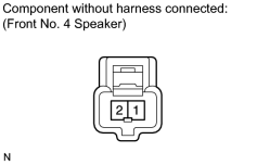
INSPECT FRONT NO. 4 SPEAKER ASSEMBLY |
|
(a) Disconnect the F6 speaker connector. |
(b) Measure the resistance according to the value(s) in the table below.
Standard Resistance:
|
Tester Connection |
Condition |
Specified Condition |
|---|---|---|
|
1 - 2 |
Always |
6.0 +/-1.0 Ω |
|
|
10. |
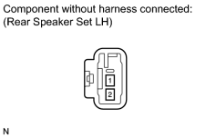
INSPECT REAR SPEAKER SET LH |
|
(a) Disconnect the J17 speaker connector. |
(b) Measure the resistance according to the value(s) in the table below.
Standard Resistance:
|
Tester Connection |
Condition |
Specified Condition |
|---|---|---|
|
1 - 2 |
Always |
6.0 +/-1.0 Ω |
|
|
11. |
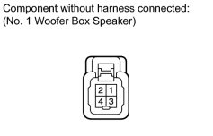
INSPECT NO. 1 WOOFER BOX SPEAKER ASSEMBLY |
|
(a) Disconnect the L4 speaker connector. |
(b) Measure the resistance according to the value(s) in the table below.
Standard Resistance:
|
Tester Connection |
Condition |
Specified Condition |
|---|---|---|
|
1 - 2 |
Always |
8.0 Ω |
|
|
12. |
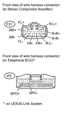
CHECK HARNESS AND CONNECTOR (STEREO COMPONENT AMPLIFIER - SPEAKER) |
|
(a) Disconnect the F31 amplifier connector. |
(b) Disconnect the P2 ECU connector.*
(c) Measure the resistance according to the value(s) in the table below.
Standard Resistance:
|
Tester Connection |
Condition |
Specified Condition |
|---|---|---|
|
F31-1 (RR+) - Body ground |
Always |
10 kΩ or higher |
|
F31-5 (RR-) - Body ground |
||
|
F31-3 (R-L+) - Body ground |
||
|
F31-9 (R-L-) - Body ground |
||
|
F31-4 (R-R+) - Body ground |
||
|
F31-10 (R-R-) - Body ground |
||
|
F31-2 (FL+) - Body ground |
||
|
F31-6 (FL-) - Body ground |
||
|
F31-7 (FR-) - Body ground |
||
|
F31-8 (FR+) - Body ground |
||
|
P2-2 (SPO+)* - Body ground |
||
|
P2-3 (SPO-)* - Body ground |
*: w/ LEXUS Link System
|
|
13. |
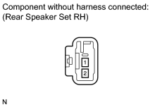
INSPECT REAR SPEAKER SET RH |
|
(a) Disconnect the J15 speaker connector. |
(b) Measure the resistance according to the value(s) in the table below.
Standard Resistance:
|
Tester Connection |
Condition |
Specified Condition |
|---|---|---|
|
1 - 2 |
Always |
6.0 +/-1.2 Ω |
|
|
14. |
INSPECT REAR NO. 2 SPEAKER ASSEMBLY |
|
(a) Disconnect the rear No. 2 speaker connectors. |
(b) Measure the resistance according to the value(s) in the table below.
Standard Resistance:
|
Tester Connection |
Condition |
Specified Condition |
|---|---|---|
|
1 - 2 |
Always |
6.0 +/-1.0 Ω |
|
|
15. |
CHECK REAR NO. 3 SPEAKER ASSEMBLY |
(a) Disconnect the rear No. 3 speaker connectors.
(b) Interchange the rear No. 3 speaker LH with RH.
(c) Check that the malfunction disappears.
OK:
Malfunction disappears.
HINT:
- Connect all the connectors to the rear No. 3 speakers.
- When there is a possibility that either the right or left rear speaker is defective, inspect by interchanging the right one with the left one.
- Perform the inspection above on both the LH and RH sides.
|
|
16. |
INSPECT FRONT NO. 2 SPEAKER ASSEMBLY |
|
(a) Disconnect the F8 and F7 speaker connectors. |
(b) Measure the resistance according to the value(s) in the table below.
Standard Resistance:
|
Tester Connection |
Condition |
Specified Condition |
|---|---|---|
|
1 - 2 |
Always |
Below 1 Ω |
|
3 - 4 |
Always |
Below 1 Ω |
|
2 - 4 |
Always |
6.0 +/-1.0 Ω |
|
|
17. |
CHECK FRONT NO. 3 SPEAKER ASSEMBLY |
(a) Disconnect the F14 and F13 speaker connectors.
(b) Interchange the front No. 3 speaker LH with RH.
(c) Check that the malfunction disappears.
OK:
Malfunction disappears.
HINT:
- Connect all the connectors to the front No. 3 speakers.
- When there is a possibility that either the right or left front speaker is defective, inspect by interchanging the right one with the left one.
- Perform the inspection above on both the LH and RH sides.
|
|
18. |
CHECK HARNESS AND CONNECTOR (FRONT NO. 2 SPEAKER - FRONT NO. 3 SPEAKER) |
|
(a) Disconnect the F8, F7, F14 and F13 speaker connectors. |
(b) Measure the resistance according to the value(s) in the table below.
Standard Resistance:
for LH
for RH
|
Tester Connection |
Condition |
Specified Condition |
|---|---|---|
|
F8-2 (TWL+) - F14-1 |
Always |
Below 1 Ω |
|
F8-4 (TWL-) - F14-2 |
||
|
F8-2 (TWL+) - Body ground |
Always |
10 kΩ or higher |
|
F8-4 (TWL-) - Body ground |
|
Tester Connection |
Condition |
Specified Condition |
|---|---|---|
|
F7-2 (TWR+) - F13-1 |
Always |
Below 1 Ω |
|
F7-4 (TWR-) - F13-2 |
||
|
F7-2 (TWR+) - Body ground |
Always |
10 kΩ or higher |
|
F7-4 (TWR-) - Body ground |
|
|
19. |
CHECK VEHICLE EQUIPMENT |
(a) Check if the vehicle is equipped with the LEXUS Link System.
Result
|
Result |
Proceed to |
|---|---|
|
w/ LEXUS Link System |
A |
|
w/o LEXUS Link System |
B |
|
|
20. |
CHECK HARNESS AND CONNECTOR (TELEPHONE ECU - STEREO COMPONENT AMPLIFIER AND FRONT NO. 2 SPEAKER RH) |
|
(a) Disconnect the F31 amplifier connector. |
(b) Disconnect the F7 speaker connector.
(c) Disconnect the P2 ECU connector.
(d) Measure the resistance according to the value(s) in the table below.
Standard Resistance:
|
Tester Connection |
Condition |
Specified Condition |
|---|---|---|
|
F7-1 (+) - P2-2 (SPO+) |
Always |
Below 1 Ω |
|
F7-3 (-) - P2-3 (SPO-) |
||
|
F31-8 (FR+) - P2-10 (SPI+) |
||
|
F31-7 (FR-) - P2-11 (SPI-) |
||
|
F7-1 (+) - Body ground |
Always |
10 kΩ or higher |
|
F7-3 (-) - Body ground |
||
|
F31-8 (FR+) - Body ground |
||
|
F31-7 (FR-) - Body ground |
|
|
21. |
REPLACE STEREO COMPONENT AMPLIFIER WITH NORMAL ONE AND CHECK |
(a) Replace the stereo component amplifier with a normal one and check if the same problem occurs again
 .
.
OK:
Same problem does not occur.
|
|
22. |
CHECK DTC |
(a) Disconnect the F3 and F31 amplifier connectors.
(b) Clear the DTCs.
(c) Check if DTC 74-40 is output.
OK:
DTC 74-40 is not output.
|
|
23. |
CHECK DTC |
(a) Reconnect the F31 amplifier connector.
(b) Clear the DTCs.
(c) Check if DTC 74-40 is output.
OK:
DTC 74-40 is not output.
|
|
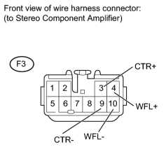
24. |
CHECK HARNESS AND CONNECTOR (STEREO COMPONENT AMPLIFIER - SPEAKER) |
|
(a) Disconnect the F3 amplifier connector. |
(b) Measure the resistance according to the value(s) in the table below.
Standard Resistance:
|
Tester Connection |
Condition |
Specified Condition |
|---|---|---|
|
F3-3 (CTR+) - Body ground |
Always |
10 kΩ or higher |
|
F3-9 (CTR-) - Body ground |
Always |
10 kΩ or higher |
|
F3-4 (WFL+) - Body ground |
Always |
10 kΩ or higher |
|
F3-10 (WFL-) - Body ground |
Always |
10 kΩ or higher |
|
|
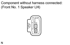
25. |
INSPECT FRONT NO. 1 SPEAKER ASSEMBLY LH |
|
(a) Disconnect the I10 speaker connector. |
(b) Measure the resistance according to the value(s) in the table below.
Standard Resistance:
|
Tester Connection |
Condition |
Specified Condition |
|---|---|---|
|
1 - 2 |
Always |
3 Ω |
|
|
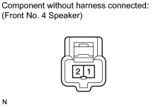
26. |
INSPECT FRONT NO. 4 SPEAKER ASSEMBLY |
|
(a) Disconnect the F6 speaker connector. |
(b) Measure the resistance according to the value(s) in the table below.
Standard Resistance:
|
Tester Connection |
Condition |
Specified Condition |
|---|---|---|
|
1 - 2 |
Always |
6 Ω |
|
|
27. |
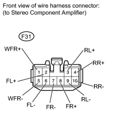
CHECK HARNESS AND CONNECTOR (STEREO COMPONENT AMPLIFIER - SPEAKER) |
|
(a) Disconnect the F31 amplifier connector. |
(b) Measure the resistance according to the value(s) in the table below.
Standard Resistance:
|
Tester Connection |
Condition |
Specified Condition |
|---|---|---|
|
F31-1 (WFR+) - Body ground |
Always |
10 kΩ or higher |
|
F31-6 (FL-) - Body ground |
Always |
10 kΩ or higher |
|
F31-2 (FL+) - Body ground |
Always |
10 kΩ or higher |
|
F31-7 (FR-) - Body ground |
Always |
10 kΩ or higher |
|
F31-4 (RR+) - Body ground |
Always |
10 kΩ or higher |
|
F31-3 (RL+) - Body ground |
Always |
10 kΩ or higher |
|
F31-8 (FR+) - Body ground |
Always |
10 kΩ or higher |
|
F31-10 (RR-) - Body ground |
Always |
10 kΩ or higher |
|
F31-9 (RL-) - Body ground |
Always |
10 kΩ or higher |
|
F31-5 (WFR-) - Body ground |
Always |
10 kΩ or higher |
|
|
28. |
INSPECT FRONT NO. 1 SPEAKER ASSEMBLY RH |
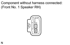
|
(a) Disconnect the I1 speaker connector. |
(b) Measure the resistance according to the value(s) in the table below.
Standard Resistance:
|
Tester Connection |
Condition |
Specified Condition |
|---|---|---|
|
1 - 2 |
Always |
3 Ω |
|
|
29. |
INSPECT REAR SPEAKER SET |
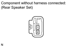
|
(a) Disconnect the J17 and J15 speaker connectors. |
(b) Measure the resistance according to the value(s) in the table below.
Standard Resistance:
|
Tester Connection |
Condition |
Specified Condition |
|---|---|---|
|
1 - 2 |
Always |
4 Ω |
|
|
30. |
INSPECT FRONT NO. 2 SPEAKER ASSEMBLY |
|
|
(a) Disconnect the F8 and F7 speaker connectors. |
(b) Measure the resistance according to the value(s) in the table below.
Standard Resistance:
|
Tester Connection |
Condition |
Specified Condition |
|---|---|---|
|
1 - 2 |
Always |
Below 1 Ω |
|
3 - 4 |
Always |
Below 1 Ω |
|
2 - 4 |
Always |
4 Ω |
|
|
31. |
INSPECT FRONT NO. 3 SPEAKER ASSEMBLY |
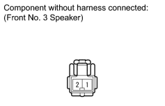
|
(a) Disconnect the F14 and F13 speaker connectors. |
(b) Measure the resistance according to the value(s) in the table below.
Standard Resistance:
|
Tester Connection |
Condition |
Specified Condition |
|---|---|---|
|
1 - 2 |
Always |
4 Ω |
|
|
32. |
CHECK HARNESS AND CONNECTOR (FRONT NO. 2 SPEAKER - FRONT NO. 3 SPEAKER) |
|
|
(a) Disconnect the F8, F7, F14 and F13 speaker connectors. |
(b) Measure the resistance according to the value(s) in the table below.
Standard Resistance:
for LH
for RH
|
Tester Connection |
Condition |
Specified Condition |
|---|---|---|
|
F8-2 (TWL+) - F14-1 |
Always |
Below 1 Ω |
|
F8-4 (TWL-) - F14-2 |
||
|
F8-2 (TWL+) - Body ground |
Always |
10 kΩ or higher |
|
F8-4 (TWL-) - Body ground |
|
Tester Connection |
Condition |
Specified Condition |
|---|---|---|
|
F7-2 (TWR+) - F13-1 |
Always |
Below 1 Ω |
|
F7-4 (TWR-) - F13-2 |
||
|
F7-2 (TWR+) - Body ground |
Always |
10 kΩ or higher |
|
F7-4 (TWR-) - Body ground |
|
|
33. |
CHECK VEHICLE EQUIPMENT |
(a) Check if the vehicle is equipped with the LEXUS Link System.
Result
|
Result |
Proceed to |
|---|---|
|
w/ LEXUS Link System |
A |
|
w/o LEXUS Link System |
B |
|
|
34. |
CHECK HARNESS AND CONNECTOR (TELEPHONE ECU - STEREO COMPONENT AMPLIFIER AND FRONT NO. 2 SPEAKER LH) |
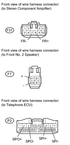
|
(a) Disconnect the F31 amplifier connector. |
(b) Disconnect the F7 speaker connector.
(c) Disconnect the P2 ECU connector.
(d) Measure the resistance according to the value(s) in the table below.
Standard Resistance:
|
Tester Connection |
Condition |
Specified Condition |
|---|---|---|
|
F7-1 (+) - P2-2 (SPO+) |
Always |
Below 1 Ω |
|
F7-3 (-) - P2-3 (SPO-) |
||
|
F31-8 (FR+) - P2-10 (SPI+) |
||
|
F31-7 (FR-) - P2-11 (SPI-) |
||
|
F7-1 (+) - Body ground |
Always |
10 kΩ or higher |
|
F7-3 (-) - Body ground |
||
|
F31-8 (FR+) - Body ground |
||
|
F31-7 (FR-) - Body ground |
|
|
35. |
REPLACE STEREO COMPONENT AMPLIFIER WITH NORMAL ONE AND CHECK |
(a) Replace the stereo component amplifier with a normal one and check if the same problem occurs again
.
OK:
Same problem does not occur.
|

|

|