| Last Modified: 11-27-2007 | 1.6 J | |
| Service Category: Audio/Visual/Telematics | Section: Audio/Video | |
| Model Year: 2008 | Model: LX570 | Doc ID: RM000002F1M00IX |
| Title: AUDIO / VIDEO: AUDIO AND VISUAL SYSTEM: DESCRIPTION (2008 LX570) | ||
|
Vehicle Speed Signal Circuit between Stereo Component Amplifier and Combination Meter |
DESCRIPTION
The stereo component amplifier performs switch operation control during driving by receiving a vehicle speed signal from the combination meter.
WIRING DIAGRAM
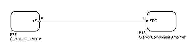
INSPECTION PROCEDURE
PROCEDURE
|
1. |
CHECK OPERATION OF SPEEDOMETER |
(a) Drive the vehicle and check if the function of the speedometer in the combination meter is normal.
OK:
Actual vehicle speed and the speed indicated on the speedometer are the same.
HINT:
The vehicle speed sensor is functioning normally when the indication on the speedometer is normal.
|

|
2. |
CHECK HARNESS AND CONNECTOR (STEREO COMPONENT AMPLIFIER - COMBINATION METER) |
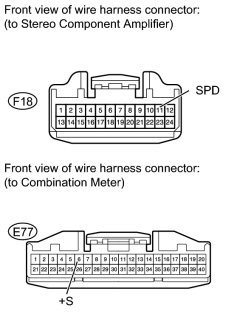
|
(a) Disconnect the F18 amplifier connector. |
(b) Disconnect the E77 meter connector.
(c) Measure the resistance according to the value(s) in the table below.
Standard Resistance:
|
Tester Connection |
Condition |
Specified Condition |
|---|---|---|
|
F18-11 (SPD) - E77-6 (+S) |
Always |
Below 1 Ω |
|
F18-11 (SPD) - Body ground |
Always |
10 kΩ or higher |
|

|

|