| Last Modified: 11-27-2007 | 1.6 J | |
| Service Category: Audio/Visual/Telematics | Section: Audio/Video | |
| Model Year: 2008 | Model: LX570 | Doc ID: RM000002IPX00BX |
| Title: AUDIO / VIDEO: REAR SEAT ENTERTAINMENT SYSTEM: DESCRIPTION (2008 LX570) | ||
|
Display Signal Circuit between Multi-display Controller and Television Display |
DESCRIPTION
This is the display signal circuit from the multi-display selector to the television display.
HINT:
"Multi-display Controller" refers to the multi-display selector.
WIRING DIAGRAM
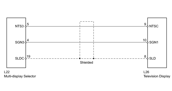
INSPECTION PROCEDURE
PROCEDURE
|
1. |
CHECK TELEVISION DISPLAY ASSEMBLY |
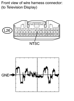
|
(a) Disconnect the L26 display connector. |
(b) Using an oscilloscope, check the signal waveform between each terminal and the body ground according to the conditions shown in the chart below.
Measurement Condition
|
Item |
Content |
|---|---|
|
Terminal No. (Symbol) |
L26-9 (NTSC) - Body ground |
|
Tool Setting |
200 mV/DIV., 10 μsec./DIV. |
|
Condition |
DVD displayed on television display |
OK:
Waveform is as shown in the illustration.
|

|
2. |
CHECK HARNESS AND CONNECTOR (MULTI-DISPLAY SELECTOR - TELEVISION DISPLAY ASSEMBLY) |
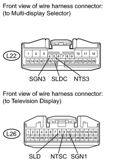
|
(a) Disconnect the L22 selector connector. |
(b) Disconnect the L26 display connector.
(c) Measure the resistance according to the value(s) in the table below.
Standard Resistance:
|
Tester Connection |
Condition |
Specified Condition |
|---|---|---|
|
L22-5 (NTS3) - L26-9 (NTSC) |
Always |
Below 1 Ω |
|
L22-4 (SGN3) - L26-10 (SGN1) |
||
|
L22-19 (SLDC) - L26-8 (SLD) |
||
|
L22-5 (NTS3) - Body ground |
Always |
10 kΩ or higher |
|
L22-4 (SGN3) - Body ground |
||
|
L22-19 (SLDC) - Body ground |
|

|

|