- Engine switch on (IG)
- Driver side duct sensor temperature: 25°C (77°F)
| Last Modified: 11-27-2007 | 1.6 U | |
| Service Category: Vehicle Interior | Section: Heating/Air Conditioning | |
| Model Year: 2008 | Model: LX570 | Doc ID: RM000002LIP008X |
| Title: HEATING / AIR CONDITIONING: AIR CONDITIONING SYSTEM: TERMINALS OF ECU (2008 LX570) | ||
TERMINALS OF ECU
1. CHECK AIR CONDITIONING AMPLIFIER ASSEMBLY
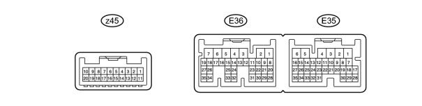
(a) Disconnect the E36, E35 and z45 air conditioning amplifier connectors.
(b) Measure the voltage and resistance according to the value(s) in the table below.
|
Terminal No. (Symbol) |
Wiring Color |
Terminal Description |
Condition |
Specified Condition |
|---|---|---|---|---|
|
E36-6 (+B1) - E36-1 (GND) |
R - W-B |
Battery power source |
Always |
11 to 14 V |
|
E36-7 (+B2) - E36-1 (GND) |
R - W-B |
Battery power source |
Always |
11 to 14 V |
|
z45-3 (B BUS) - z45-1 (BUS G) |
- |
Power supply for BUS IC (for front) |
Always |
11 to 14 V |
|
z45-10 (B BUS) - z45-8 (BUS G) |
- |
Power supply for BUS IC (for front) |
Always |
11 to 14 V |
|
E36-5 (IG+) - E36-1 (GND) |
G - W-B |
Ignition power supply |
Engine switch on (IG) |
11 to 14 V |
|
Engine switch off |
Below 1 V |
|||
|
E36-14 (RBBU) - E36-12 (RBUG) |
L - BR |
Power supply for BUS IC (for rear) |
Always |
11 to 14 V |
|
E35-25 (TR3) - Body ground |
V - Body ground |
Ground |
|
5000 +/-150 Ω |
|
E35-26 (TR4) - Body ground |
W - Body ground |
Ground |
|
5000 +/-150 Ω |
|
E35-16 (SG-2) - Body ground |
G - Body ground |
Ground for pressure sensor |
Always |
Below 1 Ω |
|
E35-29 (SG-5) - Body ground |
G - Body ground |
Ground for compressor signal |
Always |
Below 1 Ω |
|
E36-2 (E1) - Body ground |
W-B - Body ground |
Ground |
Always |
Below 1 Ω |
|
E36-1 (GND) - Body ground |
W-B - Body ground |
Ground |
Always |
Below 1 Ω |
|
E35-6 (E2) - Body ground |
W-B - Body ground |
Ground |
Always |
Below 1 Ω |
|
E35-32 (SG-1) - Body ground |
B - Body ground |
Ground for room temperature sensor (for front) |
Always |
Below 1 Ω |
|
z45-6 (SGA) - Body ground |
- |
Ground for evaporator temperature sensor |
Always |
Below 1 Ω |
|
z45-1 (BUS G) - Body ground |
- |
Ground for BUS IC (for front) |
Always |
Below 1 Ω |
|
z45-8 (BUS G) - Body ground |
- |
Ground for BUS IC (for front) |
Always |
Below 1 Ω |
|
E35-34 (SGND) - Body ground |
BR - Body ground |
Ground for duct sensor (for driver side) |
Always |
Below 1 Ω |
|
E35-12 (SG-9) - Body ground |
L - Body ground |
Ground for duct sensor (for passenger side) |
Always |
Below 1 Ω |
|
E35-2 (SG-6) - Body ground |
G - Body ground |
Ground for room temperature sensor signal (for rear LH and rear RH) |
Always |
Below 1 Ω |
|
E36-12 (RBUG) - Body ground |
BR - Body ground |
Ground for BUS IC (for rear) |
Always |
Below 1 Ω |
|
E35-1 (SG) - Body ground |
P - Body ground |
Ground for evaporator temperature sensor signal (for rear) |
Always |
Below 1 Ω |
If the result is not as specified, there may be a malfunction on the wire harness side.
(c) Reconnect the E36, E35 and z45 air conditioning amplifier connectors.
(d) Measure the voltage according to the value(s) in the table below.
|
Terminal No. (Symbol) |
Wiring Color |
Terminal Description |
Condition |
Specified Condition |
|---|---|---|---|---|
|
E36-25 (CFN+) - Body ground |
R - Body ground |
Condenser FAN operation signal |
Engine switch on (IG) |
11 to 14 V |
|
E36-33 (COOL) - Body ground |
W - Body ground |
Cool box operation signal |
Engine switch on (IG) Cool box switch on |
Below 1 V |
|
Engine switch on (IG) Cool box switch off |
11 to 14 V |
|||
|
E36-29 (AC1) - Body ground |
L - Body ground |
Compressor operation signal |
Engine switch on (IG) A/C switch off |
11 to 14 V |
|
Engine switch on (IG) A/C switch on |
Below 1 V |
|||
|
E36-22 (ACT) - Body ground |
G - Body ground |
Compressor operation signal |
Engine switch on (IG) ACT signal off |
4.5 to 5.5 V |
|
Engine switch on (IG) ACT signal on |
Below 1 V |
|||
|
E35-28 (LOCK) - E35-29 (SG-5) |
L - G |
Air compressor lock sensor signal |
Engine idling A/C switch on Blower switch lo |
Pulse generation (see waveform 1) |
|
E35-10 (TAM) - E35-16 (SG-2) |
V - G |
Ambient temperature sensor signal |
Engine switch on (IG) Ambient temperature: 25°C (77°F) |
1.4 to 1.6 V |
|
Engine switch on (IG) Ambient temperature: 50°C (122°F) |
0.7 to 0.9 V |
|||
|
E35-27 (S5-1) - E35-16 (SG-2) |
LG - G |
Power supply for pressure sensor |
Engine switch on (IG) |
4.5 to 5.5 V |
|
E35-20 (PRE) - E35-16 (SG-2) |
R - G |
Air conditioning pressure sensor signal |
Refrigerant pressure: Normal pressure (less than 3.0732 MPa [31.4 kgf/cm2, 445 psi] and more than 0.1762 MPa [1.8 kgf/cm2, 25 psi]) |
1.0 to 4.8 V |
|
Refrigerant pressure: Abnormal (less than 0.1762 MPa [1.8 kgf/cm2, 25 psi]) |
Below 1 V |
|||
|
Refrigerant pressure: Abnormal (more than 3.0732 MPa [31.4 kgf/cm2, 445 psi]) |
4.8 V or higher |
|||
|
E36-18 (MGC) - E36-1 (GND) |
R - W-B |
A/C compressor magnetic clutch operation signal |
Engine idling Blower switch lo A/C switch on |
Below 1 V |
|
E36-3 (BLW) - E36-1 (GND) |
R - W-B |
Blower motor control signal |
Engine switch on (IG) Blower switch lo |
Pulse generation (see waveform 2) |
|
E35-30 (SG-4) - E35-23 (DGS) |
L - L |
Exhaust gas sensor signal (CO, HC) |
30 seconds after engine switch on (IG) and sensor exposed to exhaust gas |
1.0 to 4.5 V |
|
E35-30 (SG-4) - E35-24 (DGS1) |
L - W |
Exhaust gas sensor signal (NOx) |
30 seconds after engine switch on (IG) and sensor exposed to exhaust gas |
1.0 to 4.5 V |
|
E35-9 (TR) - E35-32 (SG-1) |
W - B |
Room temperature sensor signal (for front) |
Engine switch on (IG) Front side interior temperature: 25°C (77°F) |
1.9 to 2.1 V |
|
Room temperature sensor signal (for front) |
Engine switch on (IG) Front side interior temperature: 50°C (122°F) |
1.0 to 2.0 V |
||
|
E35-7 (TSD) - Body ground |
LG - Body ground |
Driver side solar sensor signal |
Engine switch on (IG) Solar sensor subjected to electric light |
0.8 to 4.3 V |
|
E35-8 (TSP) - Body ground |
GR - Body ground |
Passenger side solar sensor signal |
Engine switch on (IG) Solar sensor subjected to electric light |
0.8 to 4.3 V |
|
z45-7 (TEA) - z45-6 (SGA) |
- |
Evaporator temperature sensor signal |
Engine switch on (IG) Evaporator temperature: 15°C (59°F) |
1.0 to 1.2 V |
|
z45-2 (BUS) - z45-1 (BUS G) |
- |
BUS IC control signal (for front) |
Engine switch on (IG) |
Pulse generation |
|
z45-9 (BUS) - z45-8 (BUS G) |
- |
BUS IC control signal (for front) |
Engine switch on (IG) |
Pulse generation |
|
E35-18 (TR) - E35-2 (SG-6) |
R - G |
Room temperature sensor signal (for rear LH) |
Engine switch on (IG) Vehicle interior temperature: 25°C (77°F) |
1.9 to 2.1 V |
|
Engine switch on (IG) Vehicle interior temperature: 50°C (122°F) |
1.0 to 1.2 V |
|||
|
E35-19 (TR7) - E35-2 (SG-6) |
R - G |
Room temperature sensor signal (for rear RH) |
Engine switch on (IG) Vehicle interior temperature: 25°C (77°F) |
1.9 to 2.1 V |
|
Engine switch on (IG) Vehicle interior temperature: 50°C (122°F) |
1.0 to 1.2 V |
|||
|
E36-13 (RBUS) - E36-12 (RBUG) |
R - BR |
BUS IC control signal (for rear) |
Engine switch on (IG) |
Pulse generation |
|
E35-17 (TEC) - E35-1 (SG) |
W - P |
Evaporator temperature sensor signal (for rear) |
Engine switch on (IG) Evaporator temperature: 15°C (59°F) |
1.4 to 1.8 V |
|
E36-31 (ALT) - Body ground |
R - Body ground |
Generator signal |
Engine idling |
Pulse generation |
|
E36-27 (PTC1) - Body ground |
R - Body ground |
PTC1 heater relay operation signal |
Engine idling Set temperature: Hi Engine coolant temperature: Below 65°C (149°F) Ambient temperature: Below 10°C (50°F) Blower switch off → lo |
Below 1 V → 11 to 14 V |
|
E36-26 (PTC2) - Body ground |
R - Body ground |
PTC2 heater relay operation signal |
||
|
E36-35 (PTC3) - Body ground |
R - Body ground |
PTC3 heater relay operation signal |
||
|
E36-17 (BLWH) - E36-1 (GND) |
L - W-B |
Blower motor control signal (for rear) |
Engine switch on (IG) Blower switch lo |
Pulse generation (see waveform 3) |
|
E36-19 (RMGV) - E36-1 (GND) |
B - W-B |
Rear cooling unit expansion valve signal |
Engine switch on (IG) |
11 to 14 V |
If the result is not as specified, the air conditioning amplifier assembly may have a malfunction.
|
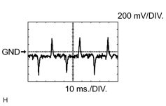
(e) Using an oscilloscope, check waveform 1.
HINT:
When the rear blower level is increased, the duty ratio changes accordingly. |
|
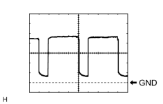
(f) Using an oscilloscope, check waveform 2.
HINT:
When the blower level is increased, the duty ratio changes accordingly. |
|
|
(g) Using an oscilloscope, check waveform 3.
HINT:
When the rear blower level is increased, the duty ratio changes accordingly. |
2. CHECK DISPLAY AND NAVIGATION MODULE DISPLAY*1, MULTI-DISPLAY*2
*1: w/ Navigation System
*2: w/o Navigation System

(a) Disconnect the F28 display connector.
(b) Measure the resistance and voltage according to the value(s) in the table below.
|
Terminal No. (Symbol) |
Wiring Color |
Terminal Description |
Condition |
Specified Condition |
|---|---|---|---|---|
|
F28-1 (+B1) - F28-10 (GND1) |
R - W-B |
Battery |
Always |
11 to 14 V |
|
F28-2 (ACC) - F28-10 (GND1) |
GR - W-B |
Accessory (ON) |
Engine switch off |
Below 1 V |
|
F28-2 (ACC) - F28-10 (GND1) |
GR - W-B |
Accessory (ON) |
Engine switch on (ACC) |
11 to 14 V |
|
F28-3 (IG) - F28-10 (GND1) |
G - W-B |
Ignition (ON) |
Engine switch off |
Below 1 V |
|
F28-3 (IG) - F28-10 (GND1) |
G - W-B |
Ignition (ON) |
Engine switch on (IG) |
11 to 14 V |
|
F28-10 (GND1) - Body ground |
W-B - Body ground |
Ground |
Always |
Below 1 Ω |
If the result is not as specified, there may be a malfunction on the wire harness side.
3. CHECK NO. 2 AIR CONDITIONING CONTROL ASSEMBLY

(a) Disconnect the E55 switch connector.
(b) Measure the resistance and voltage according to the value(s) in the table below.
|
Terminal No. (Symbol) |
Wiring Color |
Terminal Description |
Condition |
Specified Condition |
|---|---|---|---|---|
|
E55-6 (IG) - E55-1 (E) |
G - W-B |
IG power supply |
Always |
11 to 14 V |
|
E55-1 (E) - Body ground |
W-B - Body ground |
Ground |
Always |
Below 1 Ω |
If the result is not as specified, there may be a malfunction on the wire harness side.
4. CHECK MAIN BODY ECU (COWL SIDE JUNCTION BLOCK LH)
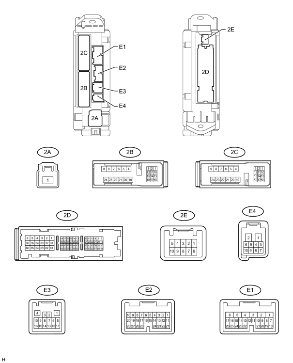
(a) Disconnect the 2A, 2B, 2D, E1, E2 and E3 ECU connectors.
(b) Measure the voltage and resistance according to the value(s) in the table below.
|
Terminal No. (Symbol) |
Wiring Color |
Terminal Description |
Condition |
Specified Condition |
|---|---|---|---|---|
|
2B-20 (BATB) - Body ground |
L - Body ground |
Battery power supply |
Always |
11 to 14 V |
|
2D-62 (GND2) - Body ground |
W-B - Body ground |
Ground |
Always |
Below 1 Ω |
|
E3-1 (GND3) - Body ground |
BR - Body ground |
Ground |
Always |
Below 1 Ω |
|
2A-1 (ACC) - 2D-62 (GND2) |
B - W-B |
ACC power supply |
Engine switch off |
Below 1 V |
|
Engine switch on (ACC) |
11 to 14 V |
|||
|
E1-6 (AM1) - 2D-62 (GND2) |
W - W-B |
Battery power supply |
Always |
11 to 14 V |
|
E2-1 (AM2) - 2D-62 (GND2) |
W - W-B |
Battery power supply |
Always |
11 to 14 V |
|
2A-1 (IG) - 2D-62 (GND2) |
B - W-B |
IG power supply |
Engine switch off |
Below 1 V |
|
Engine switch on (IG) |
11 to 14 V |
If the result is not as specified, there may be a malfunction in the wire harness.

|

|