| Last Modified: 11-27-2007 | 1.6 J | |
| Service Category: Vehicle Interior | Section: Heating/Air Conditioning | |
| Model Year: 2008 | Model: LX570 | Doc ID: RM000002LLU009X |
| Title: HEATING / AIR CONDITIONING: AIR CONDITIONING SYSTEM: DESCRIPTION (2008 LX570) | ||
|
IG Power Source Circuit |
DESCRIPTION
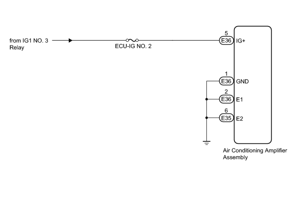
The main power source is supplied to the air conditioning amplifier assembly when the engine switch is on (IG). The power source is used for operating the air conditioning amplifier assembly and servo motor, etc.
WIRING DIAGRAM
INSPECTION PROCEDURE
HINT:
Start the engine before inspection. Check the relay or battery if the smart access system with push-button start does not start.
PROCEDURE
|
1. |
INSPECT FUSE (ECU-IG NO. 2) |
(a) Remove the ECU-IG NO. 2 fuse from the cowl side junction block LH.
(b) Measure the resistance according to the value(s) in the table below.
Standard Resistance:
|
Tester Connection |
Condition |
Specified Condition |
|---|---|---|
|
ECU-IG NO. 2 fuse |
Always |
Below 1 Ω |
|

|
2. |
CHECK HARNESS AND CONNECTOR (AIR CONDITIONING AMPLIFIER - BATTERY AND BODY GROUND) |
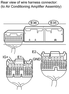
(a) Disconnect the E35 amplifier connector.
(b) Disconnect the E36 amplifier connector.
(c) Measure the voltage according to the value(s) in the table below.
Standard Voltage:
|
Tester Connection |
Switch Condition |
Specified Condition |
|---|---|---|
|
E36-5 (IG+) - Body ground |
Engine switch off |
Below 1 V |
|
Engine switch on (IG) |
11 to 14 V |
(d) Measure the resistance according to the value(s) in the table below.
Standard Resistance:
|
Tester Connection |
Condition |
Specified Condition |
|---|---|---|
|
E36-1 (GND) - Body ground |
Always |
Below 1 Ω |
|
E36-2 (E1) - Body ground |
||
|
E35-6 (E2) - Body ground |
|

|

|