| Last Modified: 11-27-2007 | 1.6 J | |
| Service Category: Vehicle Interior | Section: Heating/Air Conditioning | |
| Model Year: 2008 | Model: LX570 | Doc ID: RM000002LLW009X |
| Title: HEATING / AIR CONDITIONING: AIR CONDITIONING SYSTEM: DESCRIPTION (2008 LX570) | ||
|
Blower Motor Circuit |
DESCRIPTION
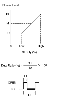
The blower motor sub-assembly (with fan) is operated by signals from the air conditioning amplifier assembly. The blower motor sub-assembly (with fan) speed signals are transmitted by changes in the duty ratio.
Duty Ratio:
The duty ratio is the ratio of the blower motor sub-assembly (with fan) OPEN time (T1) to the total of the blower motor sub-assembly (with fan) OPEN and LO time (T2).
The air conditioning amplifier assembly controls the blower motor sub-assembly (with fan) speed.
WIRING DIAGRAM
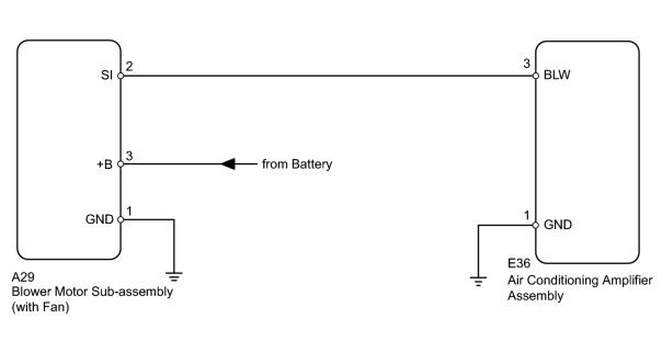
INSPECTION PROCEDURE
PROCEDURE
|
1. |
PERFORM ACTIVE TEST USING TECHSTREAM (BLOWER MOTOR SUB-ASSEMBLY) |
(a) Select the Active Test, use the Techstream to generate a control command, and then check that the blower motor operates.
Air Conditioner
|
Tester Display |
Test Part |
Control Range |
Diagnostic Note |
|---|---|---|---|
|
Blower Motor |
Blower motor sub-assembly (with fan) |
Min.: 0, Max.: 31 |
- |
Result
|
Result |
Proceed to |
|---|---|
|
Blower motor operates normally |
A |
|
Blower motor does not operate |
B |
|
Blower motor operates but does not change speed |
C |
|

|
2. |
CHECK HARNESS AND CONNECTOR (BLOWER MOTOR - BODY GROUND) |
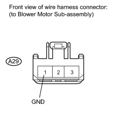
(a) Disconnect the A29 motor connector.
(b) Measure the resistance according to the value(s) in the table below.
Standard Resistance:
|
Tester Connection |
Condition |
Specified Condition |
|---|---|---|
|
A29-1 (GND) - Body ground |
Always |
Below 1 Ω |
|
|
3. |
CHECK HARNESS AND CONNECTOR (BLOWER MOTOR - BATTERY) |
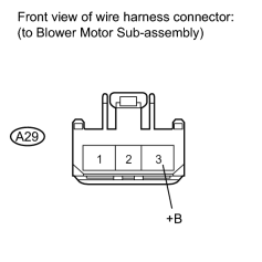
(a) Disconnect the A29 motor connector.
(b) Measure the voltage according to the value(s) in the table below.
Standard Voltage:
|
Tester Connection |
Condition |
Specified Condition |
|---|---|---|
|
A29-3 (+B) - Body ground |
Always |
11 to 14 V |
|
|
4. |
CHECK BLOWER MOTOR SUB-ASSEMBLY (SI VOLTAGE) |
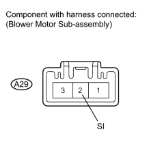
(a) Disconnect the E36 amplifier connector.
(b) Reconnect the A29 motor connector.
(c) Measure the voltage according to the value(s) in the table below.
Standard Voltage:
|
Tester Connection |
Switch Condition |
Specified Condition |
|---|---|---|
|
A29-2 (SI) - Body ground |
Engine switch on (IG) |
4.5 to 5.5 V |
|
|
5. |
CHECK HARNESS AND CONNECTOR (AIR CONDITIONING AMPLIFIER - BLOWER MOTOR) |
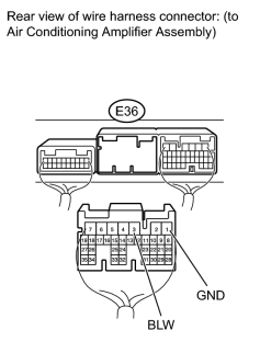
(a) Disconnect the E36 amplifier connector.
(b) Measure the voltage according to the value(s) in the table below.
Standard Voltage:
|
Tester Connection |
Switch Condition |
Specified Condition |
|---|---|---|
|
E36-3 (BLW) - E36-1 (GND) |
Engine switch on (IG) Blower switch off |
4.5 to 5.5 V |
|
|
6. |
CHECK HARNESS AND CONNECTOR (AIR CONDITIONING AMPLIFIER - BLOWER MOTOR) |
(a) Disconnect the E36 amplifier connector.
(b) Measure the voltage according to the value(s) in the table below.
Standard Voltage:
|
Tester Connection |
Switch Condition |
Specified Condition |
|---|---|---|
|
E36-3 (BLW) - E36-1 (GND) |
Engine switch on (IG) Blower switch off |
4.5 to 5.5 V |
|
|
7. |
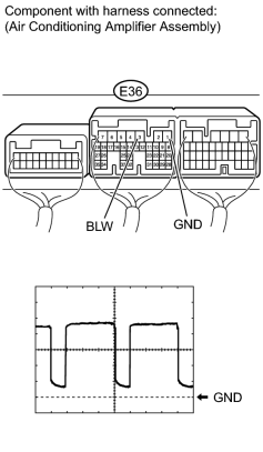
CHECK AIR CONDITIONING AMPLIFIER ASSEMBLY (BLW SIGNAL) |
|
(a) Remove the air conditioning amplifier assembly with its connectors still connected
|

(b) Using an oscilloscope, check the waveform.
Measurement Condition
|
Item |
Content |
|---|---|
|
Terminal No. (Symbol) |
E36-3 (BLW) - E36-1 (GND) |
|
Tool Setting |
1 V/DIV., 500 μs/DIV. |
|
Condition |
Engine switch on (IG) Blower switch off → on |
OK:
Waveform is as shown in the illustration.
HINT:
Waveform varies with the blower level.
|

|

|