| Last Modified: 11-27-2007 | 1.6 U | |
| Service Category: Vehicle Exterior | Section: Wiper/Washer | |
| Model Year: 2008 | Model: LX570 | Doc ID: RM000002M5U006X |
| Title: WIPER / WASHER: WIPER AND WASHER SYSTEM: TERMINALS OF ECU (2008 LX570) | ||
TERMINALS OF ECU
1. CHECK WINDSHIELD WIPER ECU
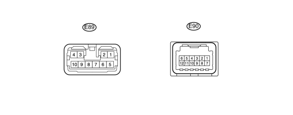
(a) Disconnect the E89 and E90 ECU connectors.
(b) Measure the voltage and resistance according to the value(s) in the table below.
|
Terminal No. (Symbol) |
Wiring Color |
Terminal Description |
Condition |
Specified Condition |
|---|---|---|---|---|
|
E89-5 (IG1l) - E90-10 (E) |
G - W-B |
Power source |
Engine switch on (IG) |
11 to 14 V |
|
E90-10 (E) - Body ground |
W-B - Body ground |
Power ground |
Always |
Below 1 Ω |
If the result is not as specified, there may be a malfunction on the wire harness side.
(c) Reconnect the E89 and E90 ECU connectors.
(d) Measure the voltage according to the value(s) in the table below.
|
Terminal No. (Symbol) |
Wiring Color |
Terminal Description |
Condition |
Specified Condition |
|---|---|---|---|---|
|
E89-7 (+SM) - Body ground |
W - Body ground |
Front wiper motor operation signal |
Front wiper operated |
11 to 14 V |
|
Front wiper stopped |
Below 1 V |
|||
|
E89-8 (WIG) - Body ground |
B - Body ground |
Front wiper motor power source circuit |
Engine switch off |
Below 1 V |
|
Engine switch on (IG) |
11 to 14 V |
|||
|
E89-10 (1S) - Body ground |
G - Body ground |
Front wiper motor power supply circuit |
Front wiper switch off |
Below 1 V |
|
Front wiper switch LO |
11 to 14 V |
|||
|
E89-9 (2S) - Body ground |
R - Body ground |
Front wiper motor power supply circuit (HI signal) |
Front wiper switch off |
Below 1 V |
|
Front wiper switch HI |
11 to 14 V |
|||
|
E90-2 (W) - Body ground |
L - Body ground |
Front washer motor power source circuit |
Front washer switch off |
11 to 14 V |
|
Front washer switch on |
Below 1 V |
If the result is not as specified, the ECU may have a malfunction.
2. CHECK NO. 2 MAIN BODY ECU
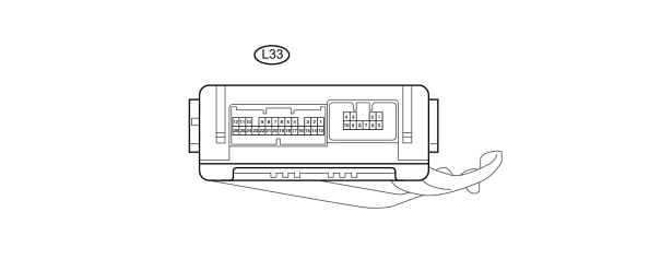
(a) Disconnect the L33 ECU connector.
(b) Measure the voltage and resistance according to the value(s) in the table below.
|
Terminal No. (Symbol) |
Wiring Color |
Terminal Description |
Condition |
Specified Condition |
|---|---|---|---|---|
|
L33-14 (BECU) - L33-7 (GND) |
R - W-B |
Power source |
Always |
11 to 14 V |
|
L33-13 (SIG) - L33-7 (GND) |
G - W-B |
Power source |
Engine switch on (IG) |
11 to 14 V |
|
L33-7 (GND) - Body ground |
W-B - Body ground |
Power source |
Always |
Below 1 Ω |
If the result is not as specified, there may be a malfunction on the wire harness side.
(c) Reconnect the L33 ECU connector.
(d) Measure the voltage according to the value(s) in the table below.
|
Terminal No. (Symbol) |
Wiring Color |
Terminal Description |
Condition |
Specified Condition |
|---|---|---|---|---|
|
L33-1 (RWSM) - Body ground |
G - Body ground |
Rear wiper motor operation signal |
Rear wiper operated |
11 to 14 V |
|
Rear wiper stopped |
Below 1 V |
|||
|
L33-4 (WRLO) - Body ground |
G - Body ground |
Rear wiper motor power supply circuit |
Rear wiper switch off |
Below 1 V |
|
Rear wiper switch on |
11 to 14 V |
|||
|
L33-5 (WRSW) - Body ground |
B - Body ground |
Rear washer motor power source circuit |
Rear washer switch off |
Below 1 V |
|
Rear washer switch on |
11 to 14 V |
If the result is not as specified, the ECU may have a malfunction.
3. CHECK WINDSHIELD WIPER SWITCH

(a) Disconnect the E16 switch connector.
(b) Measure the voltage according to the value(s) in the table below.
|
Terminal No. (Symbol) |
Wiring Color |
Terminal Description |
Condition |
Specified Condition |
|---|---|---|---|---|
|
E16-2 (+B) - E16-10 (E) |
B - W-B |
Power source circuit (from battery) |
Engine switch on (IG) |
11 to 14 V |
|
E16-10 (E) - Body ground |
W-B - Body ground |
Ground circuit |
Always |
Below 1 V |
If the result is not as specified, there may be a malfunction on the wire harness side.
4. CHECK MAIN BODY ECU (COWL SIDE JUNCTION BLOCK LH)
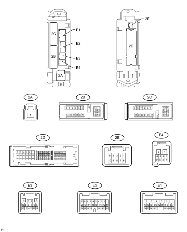
(a) Disconnect the 2D, 2B, E2 and E1 main body ECU connectors.
(b) Measure the voltage according to the value(s) in the table below.
|
Terminal No. (Symbol) |
Wiring Color |
Terminal Description |
Condition |
Specified Condition |
|---|---|---|---|---|
|
E1-6 (AM1) - 2D-62 (GND2) |
W - W-B |
ECU power supply (from battery) |
Always |
11 to 14 V |
|
E2-11 (IG2D) - 2D-62 (GND2) |
B - W-B |
IG signal circuit |
Engine switch off |
Below 1 V |
|
Engine switch on (IG) |
11 to 14 V |
|||
|
2B-22 (STP) - 2D-62 (GND2) |
R - W-B |
Stop light switch circuit |
Stop light switch off |
Below 1 V |
|
Stop light switch on |
11 to 14 V |
|||
|
2D-62 (GND2) - Body ground |
W-B - Body ground |
Ground circuit |
Always |
Below 1 V |
If the result is not as specified, there may be a malfunction on the wire harness side.
5. CHECK MAP LIGHT
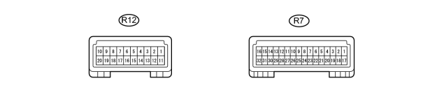
(a) Disconnect the R7 and R12 map light connectors.
(b) Measure the voltage according to the value(s) in the table below.
|
Terminal No. (Symbol) |
Wiring Color |
Terminal Description |
Condition |
Specified Condition |
|---|---|---|---|---|
|
R7-6 (+B2) - R12-20 (GND5) |
R - W-B |
ECU power supply (from battery) |
Always |
11 to 14 V |
|
R7-9 (IG) - R12-20 (GND5) |
G - W-B |
IG signal circuit |
Engine switch off |
Below 1 V |
|
Engine switch on (IG) |
11 to 14 V |
|||
|
R12-20 (GND5) - Body ground |
W-B - Body ground |
Ground circuit |
Always |
Below 1 V |
If the result is not as specified, there may be a malfunction on the wire harness side.
6. CHECK RAIN SENSOR

(a) Disconnect the R11 rain sensor connector.
(b) Measure the voltage according to the value(s) in the table below.
|
Terminal No. (Symbol) |
Wiring Color |
Terminal Description |
Condition |
Specified Condition |
|---|---|---|---|---|
|
R11-4 (SIG) - Body ground |
G - Body ground |
IG signal circuit (to IG relay) |
Engine switch off |
Below 1 V |
|
Engine switch on (IG) |
11 to 14 V |
|||
|
R11-1 (ES) - Body ground |
W - Body ground |
Ground circuit |
Always |
Below 1 V |
If the result is not as specified, there may be a malfunction on the wire harness side.
7. CHECK HEADLIGHT CLEANER CONTROL RELAY

(a) Disconnect the relay connector.
(b) Measure the voltage according to the value(s) in the table below.
|
Terminal No. (Symbol) |
Wiring Color |
Terminal Description |
Condition |
Specified Condition |
|---|---|---|---|---|
|
3 (IG) - 4 (E) |
R-B - W-B |
IG signal circuit (to IG relay) |
Engine switch off |
Below 1 V |
|
Engine switch on (IG) |
11 to 14 V |
|||
|
6 (PB) - 4 (E) |
W-G - W-B |
Headlight cleaner motor operation signal |
Headlight cleaner motor stopped |
Below 1 V |
|
Headlight cleaner motor operating |
11 to 14 V |
If the result is not as specified, there may be a malfunction on the wire harness side.
(c) Reconnect the relay connector.
(d) Measure the voltage according to the value(s) in the table below.
|
Terminal No. (Symbol) |
Wiring Color |
Terminal Description |
Condition |
Specified Condition |
|---|---|---|---|---|
|
2 (H) - 4 (E) |
LG - W-B |
Headlight cleaner switch and headlight switch operation signal |
Headlight cleaner switch off |
Below 1 V |
|
Headlight switch off |
Below 1 V |
|||
|
Headlight cleaner switch and headlight switch on |
11 to 14 V |
If the result is not as specified, the relay may have a malfunction.

|

|