| Last Modified: 11-27-2007 | 1.6 G | |
| Service Category: Drivetrain | Section: Automatic Transmission/Transaxle | |
| Model Year: 2008 | Model: LX570 | Doc ID: RM000002M9A00WX |
| Title: AB60F AUTOMATIC TRANSMISSION / TRANSAXLE: SHIFT LEVER: ON-VEHICLE INSPECTION (2008 LX570) | ||
ON-VEHICLE INSPECTION
1. INSPECT SHIFT LEVER POSITION
(a) When moving the shift lever from P to R with the engine switch on (IG) and the brake pedal depressed, make sure that it moves smoothly and correctly into position.
(b) Check that the shift lever does not stop when moving the shift lever from R to P, and check that the shift lever does not stick when moving the shift lever from D to S.
(c) Start the engine and make sure that the vehicle moves forward after moving the shift lever from N to D and moves rearward after moving the shift lever to R.
If the operation cannot be performed as specified, inspect the park/neutral position switch assembly and check the shift lever assembly installation condition.
2. CHECK SHIFT LOCK OPERATION
(a) Move the shift lever to P.
(b) Turn the engine switch off.
(c) Check that the shift lever cannot be moved from P.
(d) Turn the engine switch on (IG), depress the brake pedal and check that the shift lever can be moved to other positions.
If the operation cannot be done as specified, inspect the shift lever assembly and shift lock control unit.
3. CHECK SHIFT LOCK RELEASE BUTTON OPERATION
(a) When operating the shift lever with the shift lock release button pressed, check that the lever can be moved to any position.
If the operation cannot be performed as specified, check the shift lever assembly.
4. CHECK SHIFT LOCK CONTROL ECU
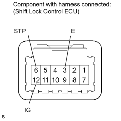
(a) Measure the voltage according to the value(s) in the table below.
HINT:
Do not disconnect the shift lock control ECU connector.
Standard Voltage:
|
Tester Connection |
Condition |
Specified Condition |
|---|---|---|
|
12 (IG) - 3 (E) |
Engine switch on (IG) |
11 to 14 V |
|
12 (IG) - 3 (E) |
Engine switch off |
Below 1 V |
|
6 (STP) - 3 (E) |
Depress brake pedal |
11 to 14 V |
|
6 (STP) - 3 (E) |
Release brake pedal |
Below 1 V |
|
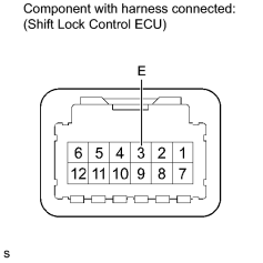
(b) Measure the resistance according to the value(s) in the table below. HINT:
Do not disconnect the shift lock control ECU connector. Standard Resistance:
|
|
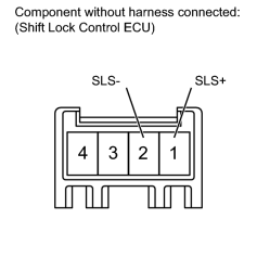
(c) Disconnect the shift lock solenoid connector from the shift lock control ECU. |
(d) Measure the voltage according to the value(s) in the table below.
HINT:
Do not disconnect the shift lock control ECU connector.
Standard Voltage:
|
Tester Connection |
Condition |
Specified Condition |
|---|---|---|
|
1 (SLS+) - 2 (SLS-) |
Engine switch off |
Below 1 V |
|
1 (SLS+) - 2 (SLS-) |
Engine switch on (IG) |
Below 1 V |
|
Engine switch on (IG) and brake pedal depressed |
11 to 14 V |
If the result is not as specified, replace the shift lever assembly.
5. CHECK SHIFT LOCK SOLENOID
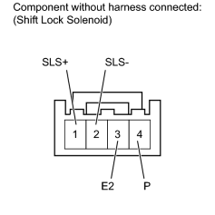
(a) Disconnect the shift lock solenoid connector from the shift lock control ECU.
(b) Measure the resistance according to the value(s) in the table below.
Standard Resistance:
|
Tester Connection |
Condition |
Specified Condition |
|---|---|---|
|
1 (SLS+) - 2 (SLS-) |
Always |
101 to 123 Ω |
|
3 (E2) - 4 (P) |
Shift lever in P |
10 kΩ or higher |
|
3 (E2) - 4 (P) |
Shift lever not in P |
Below 1 Ω |
(c) Apply 12 V battery voltage to the shift lock solenoid valve and check that the valve moves and makes an operating noise.
OK:
|
Measurement Condition |
Specified Condition |
|---|---|
|
Battery positive (+) → Terminal 1 (SLS+) Battery negative (-) → Terminal 2 (SLS-) |
Solenoid moves and makes an operating noise |
If the result is not as specified, replace the shift lever assembly.

|

|