| Last Modified: 11-27-2007 | 1.6 G | |
| Service Category: Engine/Hybrid System | Section: Starting | |
| Model Year: 2008 | Model: LX570 | Doc ID: RM000002MDT00CX |
| Title: 3UR-FE STARTING: ENGINE SWITCH: INSPECTION (2008 LX570) | ||
INSPECTION
1. INSPECT ENGINE SWITCH
(a) Measure the resistance according to the value(s) in the table below.
Standard Resistance:
|
Tester Connection |
Switch Condition |
Specified Condition |
|---|---|---|
|
7 (SS1) - 5 (GND) |
Not pushed |
10 kΩ or higher |
|
2 (SS2) - 5 (GND) |
Not pushed |
10 kΩ or higher |
|
7 (SS1) - 5 (GND) |
Pushed |
Below 1 Ω |
|
2 (SS2) - 5 (GND) |
Pushed |
Below 1 Ω |
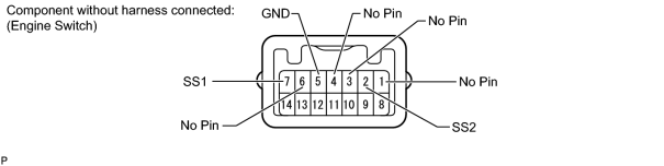
If the result is not as specified, replace the engine switch.
(b) Apply battery voltage between the terminals of the switch, and check the illumination condition of the switch.
HINT:
- If the positive (+) lead and the negative (-) lead are incorrectly connected, the engine switch indicator will not illuminate.
- If the voltage is too low, the indicator will not illuminate.
OK:
|
Measurement Condition |
Specified Condition |
|---|---|
|
Battery positive (+) → Terminal 11 (SWIL) Battery negative (-) → Terminal 5 (GND) |
Illuminates (illumination of lettering) |
|
Battery positive (+) → Terminal 12 (INDS) Battery negative (-) → Terminal 5 (GND) |
Illuminates (green) |
|
Battery positive (+) → Terminal 13 (INDW) Battery negative (-) → Terminal 5 (GND) |
Illuminates (amber) |
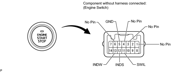
If the result is not as specified, replace the engine switch.

|

|