| Last Modified: 11-27-2007 | 1.6 J | |
| Service Category: Vehicle Interior | Section: Supplemental Restraint Systems | |
| Model Year: 2008 | Model: LX570 | Doc ID: RM000002OOK00CX |
| Title: SUPPLEMENTAL RESTRAINT SYSTEMS: AIRBAG SYSTEM: DESCRIPTION (2008 LX570) | ||
|
Diagnosis Circuit |
DESCRIPTION
DTC output mode is set by connecting terminals TC and CG of the DLC3.
DTCs are output by the blinking of the SRS warning light.
HINT:
- When each warning light stays blinking, a ground short in the wiring of terminal TC of the DLC3 or an internal ground short in each ECU is suspected.
- A DTC output mode signal is transmitted through the CAN communication system to each ECU including the center airbag sensor. Thus, when all systems do not enter DTC output mode, there may be an ECM malfunction.
WIRING DIAGRAM
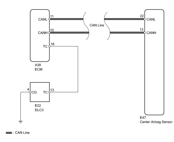
INSPECTION PROCEDURE
NOTICE:
-
w/ Navigation system:
After the engine switch is turned off, the HDD navigation system requires approximately 6 minutes to record various types of memory and settings. As a result, after turning the engine switch off, wait 6 minutes or more before disconnecting the cable from the negative (-) battery terminal.
-
When disconnecting the cable from the negative (-) battery terminal while performing repairs, some systems need to be initialized after the cable is reconnected
 .
.
PROCEDURE
|
1. |
CHECK CAN COMMUNICATION SYSTEM |
(a) Check if a CAN communication system DTC is output
.
Result
|
Result |
Proceed to |
|---|---|
|
DTC is not output |
A |
|
DTC is output |
B |
|

|
2. |
CHECK HARNESS AND CONNECTOR (DLC3 - ECM) |
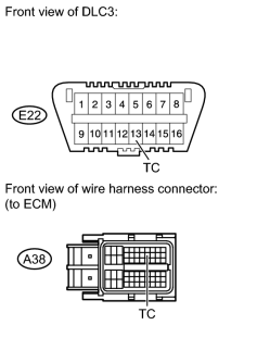
(a) Turn the engine switch off.
(b) Disconnect the A38 connector from the ECM.
(c) Measure the resistance according to the value(s) in the table below.
Standard Resistance:
|
Tester Connection |
Condition |
Specified Condition |
|---|---|---|
|
E22-13 (TC) - A38-16 (TC) |
Always |
Below 1 Ω |
|
|
3. |
CHECK HARNESS AND CONNECTOR (DLC3 - BODY GROUND) |
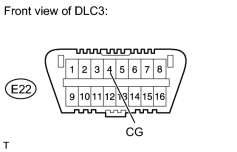
(a) Measure the resistance according to the value(s) in the table below.
Standard Resistance:
|
Tester Connection |
Condition |
Specified Condition |
|---|---|---|
|
E22-4 (CG) - Body ground |
Always |
Below 1 Ω |
|
|
4. |
CHECK HARNESS AND CONNECTOR (ECM - BODY GROUND) |
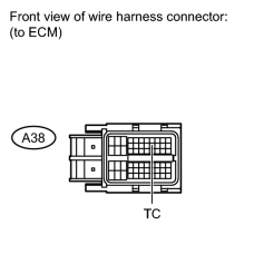
(a) Measure the resistance according to the value(s) in the table below.
Standard Resistance:
|
Tester Connection |
Condition |
Specified Condition |
|---|---|---|
|
A38-16 (TC) - Body ground |
Always |
1 MΩ or higher |
|

|

|